


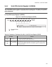
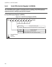
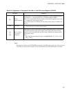
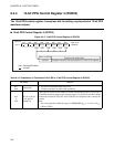
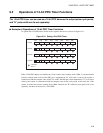


223
CHAPTER 9 12-BIT PPG TIMER
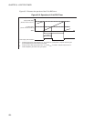
9.7 Program Example for 12-bit PPG Timer
An example of 12-bit PPG timer programming is given below.
■ Program Example for 12-bit PPG Timer
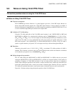
● Processing specification
• A remote control transmission frequency with a period of about 38 µs and a duty cycle of approx. 33%
is generated.
• The compare value for the PPG output pulse cycle period giving the above period of about 38 µs at the
maximum gear speed with oscillation of 12.5 MHz (F
CH
) is determined as below. The count clock is
assumed to be 4 t
INST
.
Compare value for cycle period (RCR23:SCL5 to SCL0 and RCR24:SCL11 to SCL6) = 38 µs/ (4 × 4/
10MHz) = 30
• The compare value for the "H" width of the PPG output pulse giving the duty cycle of approx. 33% is
determined as below. At this time, the "H" width is about 3 µs.
Compare value for the "H" width (RCR21:HSC5 to HSC0 and RCR22:HSC11 to HSC6) =33/100 ×
Compare value for the cycle period = 0.33 × 30 = 10
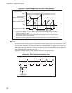
● Coding example
RCR21 EQU 0014H ; Address of 12-bit PPG control register 1
RCR22 EQU 0015H ; Address of 12-bit PPG control register 2
RCR23 EQU 0016H ; Address of 12-bit PPG control register 3
RCR24 EQU 0017H ; Address of 12-bit PPG control register 4
;------------------------Main program---------------------------------------------------------------------------------
CSEG ; [CODE SEGMENT]
:
MOV RCR21,#01001010B ; Select count clock of 4 t
INST
and set the above compare
value for "H" width.
MOV RCR22,#00H ;
MOV RCR23,#10011110B ; Specify outputs enabled and counter operation start and
set the above compare value for cycle period.
MOV RCR24,#00H ;
:
ENDS
;---------------------------------------------------------------------------------------------------------------------
END