


233
CHAPTER 10 EXTERNAL INTERRUPT CIRCUIT 1 (EDGE)
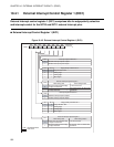
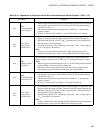
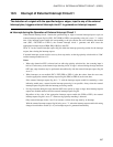
Table 10.4-1 Explanation of Functions of Each Bit in External Interrupt Control Register 1 (EIC1) (1/2)
Bit name Function
bit7
EIR1:
External interrupt
request flag bit1
• When a signal with an edge or edges corresponding to edge polarity selected by
edge polarity selection bits (SL11, SL10) is input to INT11 external interrupt
pin, this bit is set to "1".
• When this bit and interrupt request enable bit 1 (EIE1) are "1", the interrupt
request is output.
• Writing "0" clears this bit; writing "1" does not affect this bit (no change).
bit6,
bit5
SL11, SL10:
Edge polarity
selection bits 1
• These bits are used to select the polarity of an edge or edges of a signal pulse that
triggers an interrupt when the signal is input to INT11 external interrupt pin.
• When these bits provide a value of "00
B
", edge detection is not performed and
interrupt requests are not generated.
• These bits may specify "01
B
", indicating a rising edge, "10
B
", a falling edge, or
"11
B
", both edges to be detected.
Note:
If an edge is selected while edge detection is OFF, edge detection may be
performed unconditionally. Always clear the EIR0 bit after selecting an edge.
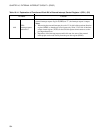
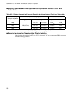
bit4
EIE1:
Interrupt request
enable bit 1
This bit enables or disables interrupt request outputs to CPU. When this bit and
external interrupt request flag bit 1 (EIR1) are "1", the interrupt request is output.
Notes:
• When using the external interrupt pin, write "0" for bit5 of the port data direction
register (DDR3) so that the pin serves inputs only.
• Regardless of the interrupt request enable bit state, the state of the external
interrupt pin can be read directly from the port data register (PDR3).
bit3
EIR0:
External interrupt
request flag bit 0
• When a signal with an edge or edges corresponding to edge polarity selected by
edge polarity selection bits (SL01, SL00) is input to INT10 external interrupt
pin, this bit is set to "1".
• When this bit and interrupt request enable bit 0 (EIE0) are "1", the interrupt
request is output.
• Writing "0" clears this bit, and writing "1" does not affect this bit.
bit2,
bit1
SL01, SL00:
Edge polarity
selection bits 0
• These bits are used to select the polarity of an edge or edges of a signal pulse that
triggers an interrupt when the signal is input to the INT10 external interrupt pin.
• When these bits provide a value of "00
B
", edge detection is not performed and
interrupt requests are not generated.
• These bits may specify "01
B
", indicating a rising edge, "10
B
", a falling edge, or
"11
B
", both edges to be detected.
Note:
If edge is selected when edge detection is OFF, edge detection may be performed
unconditionally. Always clear the EIR0 bit after selecting an edge.