


183
CHAPTER 8 8/16-BIT CAPTURE TIMER/COUNTER
8.5 8/16-bit Capture Timer/Counter of Interrupts
The 8/16-bit capture timer/counter generates an interrupt if the values set in a data
register match those set in the counter when the interval timer or counter is operating.
The interrupt level is IRQ3 when generated by the 8/16-bit capture timer/counter. When
the capture is in operation and a capture edge is detected, IRQ4 is generated.
■ 8/16-bit Capture Timer/Counter of Interrupts
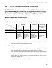
Table 8.5-1 shows the interrupt request flag bit, interrupt flag clear bit, interrupt request enable bit, and the
cause of the 8/16-bit capture timer/counter interruption.
In the 8-bit mode, timer 0 and timer 1 independently generats the interrupt request for 8/16-bit capture
timer/counter. In the 16-bit mode, timer 0 generates the interrupt request. All basic operations are the same.
Timer 0 interrupt operation in the 8-bit mode is explained here.
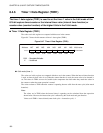
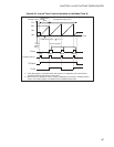
● Timer 0 interrupt operation in the 8-bit mode
The counter value is incremented according to the selected count clock, starting at 00
H
. When the counter
value matches the value set in the comparator data latch (timer 0 data register (TDR0)) corresponding to the
timer 0 data register (TDR0), the compare match detection flag bit (TCR0: TIF0) is set to "1".
In this case, when the interrupt request flag bit is allowed (when TCR0: T0IEN = 1), timer 0 generates an
interrupt request (IRQ3) to the CPU. Set the TFCR0 bit to "1" and clear the interrupt request with the
interrupt processing routine.
When the counter value matches the value set in the comparator data latch, the TIF0 bit is set to "1"
regardless of the TFCR0 bit value.
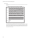
In the 8-bit mode, timer 0 and timer 1 operate independently, and because they generate the same interrupt
request (IRQ3), determination of the interrupt request flag by software may be required.
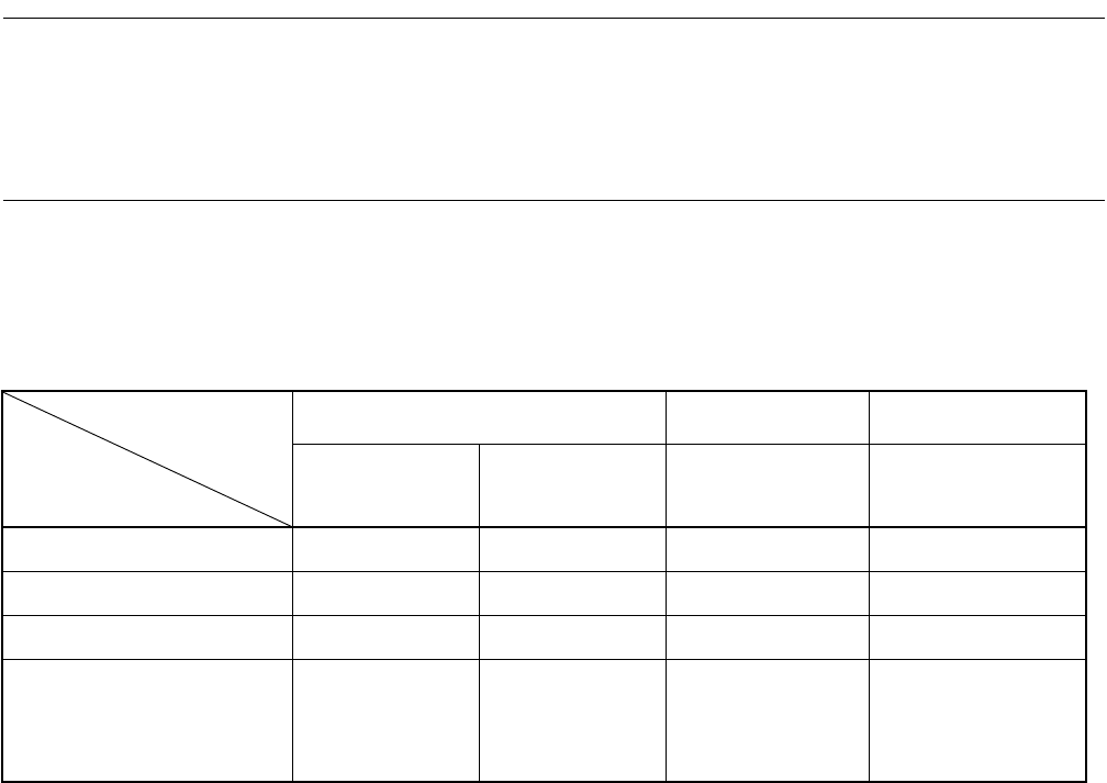
Table 8.5-1 Interrupt Control Bits and the Cause of the 8/16-bit Capture Timer/Counter Interrupt
8-bit mode 16-bit mode Capture mode
Timer 0 Timer 1 Timer 0 + timer 1
Timer 0 or timer 0 +
timer 1
Interrupt request flag bit TCR0 : TIF0 TCR1 : TIF1 TCR0 : TIF0 TCCR : CPIF
Interrupt flag clear bit TCR0 : TFCR0 TCR1 : TFCR1 TCR0 : TFCR0 TCCR : CFCLR
Interrupt request enable bit TCR0 : T0IEN TCR1 : T1IEN TCR0 : T0IEN TCCR : CPIEN
Interrupt cause
The values in
TDR0 match
those in the 8-bit
counter.
The values in
TDR1 match
those in the 8-bit
counter.
The values in
TDR0 and TDR1
match those in the
16-bit counter.
A capture edge is
detected.