


229
CHAPTER 10 EXTERNAL INTERRUPT CIRCUIT 1 (EDGE)
10.3 Pins of External Interrupt Circuit 1
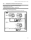
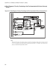
This section describes the pins associated with external interrupt circuit 1 and
illustrates a block diagram of circuitry terminating at the pins with reference to the
registers and external interrupt triggering.
■ Pins Associated with External Interrupt Circuit 1
The pins associated with external interrupt circuit 1 are the P34/TO/INT10 to P36/INT12 pins.
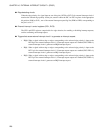
● P34/TO/INT10 pin
This pin functions as a general-purpose I/O dedicated port and may also serve 8/16-bit capture timer
outputs (TO) and external interrupt inputs (hysteresis inputs) (INT10).
If the timer 1 control register (TCR0) disables 8/16-bit capture timer outputs and, by the port data direction
register (DDR3), the pin is set to function as an input port only. The pin can also function as an external
interrupt input pin (INT10). When external interrupt 1 control register 1 (EIC1) sets edge detection to OFF,
however, no external interrupt requests are generated, and when interrupt request outputs are disabled, no
interrupt requests are output. The pin state can be read directly from the port data register (PDR3) at any
time.
● P35/INT11 and P36/INT12 pins
These pins function as a general-purpose I/O dedicated port (P35, P36) and may also serve external
interrupt inputs (hysteresis inputs) (INT11, INT12).
If, by the port data direction register (DDR3), these pins are set to function as an input port only, they also
function as external interrupt input pins (INT11, INT12). When external interrupt 1 control registers 1 and
2 (EIC1, EIC2) set edge detection to OFF, however, no external interrupt requests are generated, and when
interrupt request outputs are disabled, no interrupt requests are output. The pin state can be read directly
from the port data register (PDR3) at any time.
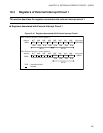
Table 10.3-1 lists the pins associated with external interrupt circuit 1.
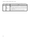
Table 10.3-1 Pins Associated with External Interrupt Circuit 1
External interrupt pin
Use for external interrupt input
(Interrupt request output enabled)
Use for input port only
(Interrupt request output or edge detection
disabled)
P34/TO/INT10
INT10 (EIC1:EIE0=1, DDR3:bit4=0,
TCR2:PEN=0)
P34(EIC1:EIE0=0 or SL01, SL00=00
B
)
P35/INT11 INT11 (EIC1:EIE1=1, DDR3:bit5=0)
P35(EIC1:EIE1=0 or SL11, SL10=00
B
)
P36/INT12 INT12 (EIC2:EIE2=1, DDR3:bit6=0)
P36(EIC2:EIE2=0 or SL21, SL20=00
B
)
INT10 to INT12: When a signal with an edge or edges corresponding to the selected edge polarity is input to these pins,
an interrupt corresponding to the pin is generated.