


282
CHAPTER 13 UART
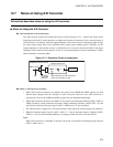
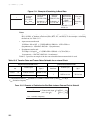
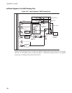
Figure 13.1-2 Example of Calculating the Baud Rate
Notes:
The baud rate is specified using the clock gear register (CS1 and CS0), clock divider registers (PR2,
PR1, and PR0), or baud rate selection registers (RC2, RC1, and RC0). For the example of calculating
the baud rate, see Table 13.1-2 .
• Asynchronous transfer mode
1/12019bps= 0.8 µs{4/F
CH
× 2.5(PR2=0,PR1=1,PR0=0)} × 1(CS1=CS0=1) ×
8(asynchronous) × 1(RC2=RC1=RC0=0) × 13(asynchronous)
• Synchronous transfer mode
1/1.25Mbps = 0.8 µs{4/F
CH
× 2.5(PR2=0,PR1=1,PR0=0)} × 1(CS1=CS0=1) ×
1(synchronous) × 1(RC2=RC1=RC0=0) × 1(synchronous)
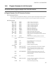
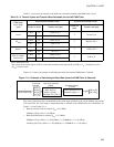
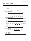
Table 13.1-3 provides an example of the baud rates selectable when an external clock is used.
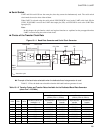
Figure 13.1-3 Example of Calculating the Baud Rate (when an External Clock is Selected)
Value of baud rate
1
=
Clock gear
selected
4/F
CH
, 8/F
CH
16/F
CH
, 64/F
CH
Clock divider
selected
(PR2,PR1,PR0)
Divided by 1, 2,
2.5, 3, 4, or 5
Baud rate
selected
(RC2,RC1,RC0)
Divided by 1, 2,
4, 8, 16, or 32
Synchronous/
asynchronous
mode selected
(SMDE)
Divided by 1 or
13
Note: When RC2 is
1 and RC1 is 1, the
divider is 1.
Clock rate
(CR)
Divided by 1,
or 8
Table 13.1-3 Transfer Cycles and Transfer Rates Selectable for an External Clock
Asynchronous transfer mode Synchronous transfer mode
Divider for baud
rate
Transfer cycle
Transfer rate
(bps) *
Divider for
baud rate
Transfer cycle
Transfer rate
(bps) *
CR=0 16
256/F
CH
or more
48828 or less
1
16/F
CH
or more
781 k or less
CR=1 64
1024/F
CH
or more
12207 or less
*: The minimum value of F
CH
specified for 12.5 MHz is external clock cycle 16/F
CH
= 1.28 µs.
F
CH
: Oscillation frequency
(min: 8/F
CH
2)
F
CH
: Oscillation frequency
Value of baud rate
1
External clock input
CR CR=0
16
64
CR=1