


246
CHAPTER 11 EXTERNAL INTERRUPT CIRCUIT 2 (LEVEL)
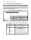
11.3 Pins of External Interrupt Circuit 2
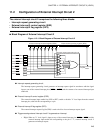
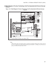
This section describes the pins associated with external interrupt circuit 2 and
illustrates a block diagram of circuitry terminating at the pins with reference to the
registers and interrupt triggering.
■ Pins Associated with External Interrupt Circuit 2
The pins associated with external interrupt circuit 2 are eight external interrupt pins.
● P00/INT20
/AN4 to P03/INT23/AN7
These external interrupt pins function as external interrupt input pins (hysteresis input) and as the pins of
the general-purpose I/O port and analog inputs.
The P00/INT20
/AN4 to P03/INT23/AN7 pins function as external interrupt input pins (INT20 to INT23) if
set to function as an input port by the corresponding bits of the port 0 data direction register (DDR0), if set
to be enabled for external interrupt inputs (ADEN=0) by the corresponding bits of the A/D enable register
(ADEN), and if external interrupt inputs are enabled (EIE2:IE20 to IE27=1) by the external interrupt 2
control register (EIE2). When set to function as an input port by the DDR0 register, the state of these pins
can be read from the port 0 data register (PDR0) at any time.
● P04/INT24
to P07/INT27
These external interrupt pins function as external interrupt input pins (hysteresis input) and also serving as
the pins of the general-purpose I/O port.
The P04/INT24
to P07/INT27 pins function as external interrupt input pins (INT24 to INT27) if set to
function as an input port by the corresponding bits of the port 0 data direction register (DDR0) and if
external interrupt inputs are enabled by the external interrupt 2 control register (EIE2). When set to
function as an input port, the state of these pins can be read from the port 0 data register (PDR0) at any
time.
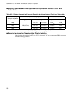
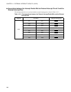
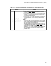
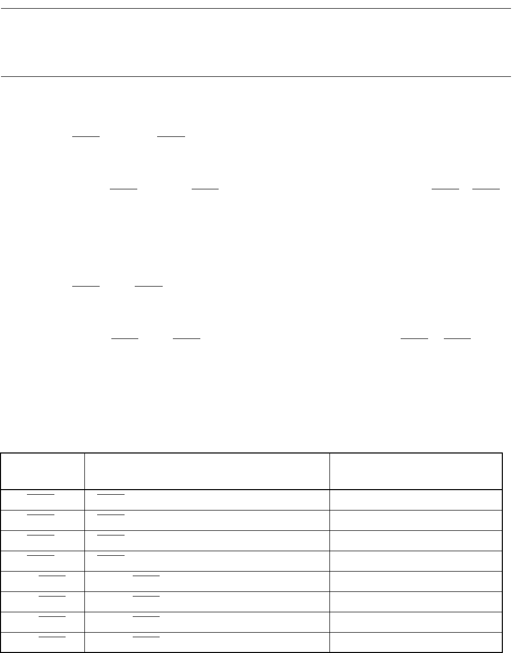
Table 11.3-1 lists the pins associated with external interrupt circuit 2.
Table 11.3-1 Pins Associated with External Interrupt Circuit 2
External
interrupt pin
Use for external interrupt input
(Interrupt input enabled)
Use for general-purpose I/O port
(Interrupt input disabled)
P00/INT20
/AN4 INT20 (EIE2:IE20=1,DDR0:bit0=0,ADEN:ADE4=0) P00 (EIE2:IE20=0)
P01/INT21
/AN5 INT21 (EIE2:IE21=1,DDR0:bit1=0,ADEN:ADE5=0) P01 (EIE2:IE21=0)
P02/INT22
/AN6 INT22 (EIE2:IE22=1,DDR0:bit2=0,ADEN:ADE6=0) P02 (EIE2:IE22=0)
P03/INT23
/AN7 INT23 (EIE2:IE23=1,DDR0:bit3=0,ADEN:ADE7=0) P03 (EIE2:IE23=0)
P04/INT24
INT24 (EIE2:IE24=1,DDR0:bit4=0) P04 (EIE2:IE24=0)
P05/INT25
INT25 (EIE2:IE25=1,DDR0:bit5=0) P05 (EIE2:IE25=0)
P06/INT26
INT26 (EIE2:IE26=1,DDR0:bit6=0) P06 (EIE2:IE26=0)
P07/INT27
INT27 (EIE2:IE27=1,DDR0:bit7=0) P07 (EIE2:IE27=0)