


145
CHAPTER 7 8-BIT PWM TIMER
7.4.2 PWM Compare Register (COMR)
The PWM compare register (COMR) is used to set an interval while the internal timer
functions are enabled. In addition, the register becomes the "H" level width of a pulse
while the PWM timer functions are enabled.
■ PWM Compare Register (COMR)
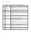
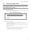
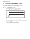
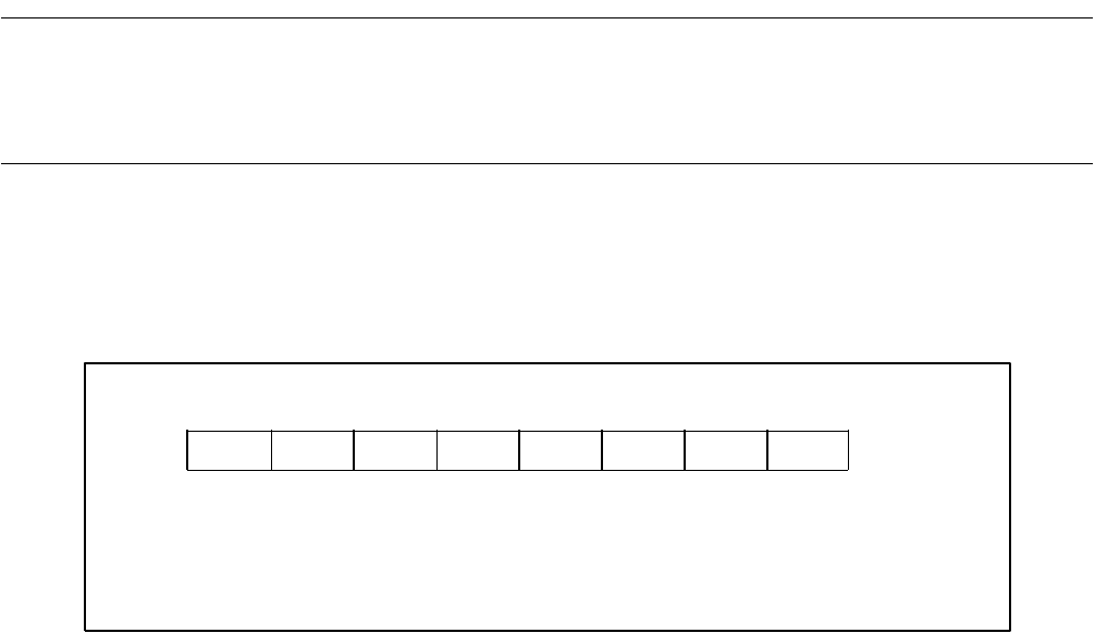
Figure 7.4-3 shows the bit configuration of a PWM compare register. Because this register is a write-only
register, an instruction to operate bits cannot be used.
Figure 7.4-3 PWM Compare Register (COMR)
● While the interval timer is operating:
Specify an interval in the register to which the value compared with the counter value is to be set.
When the settings written to this register match the counter value, the counter is cleared and "1" is set to the
interrupt request flag bit (CNTR: TIR = 1).
If a value is written to the COMR register while the counter is operating, the value takes effect at the next
cycle (after detection of a match).
Note:
The settings of the COMR register, while the interval timer is operating, can be calculated using the
following formula. The gear function, however, affects the instruction cycle.
COMR register value = interval/(count clock cycle × instruction cycle) - 1
bit7 bit6 bit5 bit4 bit3 bit2 bit1 bit0
0023
H
XXXXXXXX
B
WWWWWWWW
W
X
Address
Initial value
: Write only
: Undefined