


315
CHAPTER 14 8-BIT SERIAL I/O
14.2 Configuration of 8-Bit Serial I/O
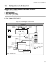
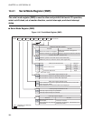
Each 8-bit serial I/O channel consists of the following four blocks:
• Shift clock control circuit
• Shift clock counter
• Serial data register (SDR)
• Serial mode register (SMR)
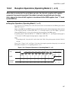
■ Block Diagram of 8-bit Serial I/O
Figure 14.2-1 Block Diagram of 8-bit Serial I/O
D0 to D7 D7 to D0
D7 to D0
P32/UI/SI
P31/UO/SO
2t
INST
8t
INST
32t
INST
SST
BDS
CKS0
CKS1
SOE
SCKE
SIOE
SIOF
IRQC
P30/UCK/SCK
2
t
INST
Internal data bus
MSB first
Transfer direction
selection
LSB first
Pin
Pin
Pin
(Shift direction)
Serial data register (SDR)
Output buffer
Output
allowance
Output
allowance
Shift clock selection
Shift clock control circuit
Serial mode register (SMR)
Overflow
Output buffer
Clear
Shift clock counter
: Instruction cycle
Interrupt request