


238
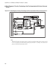
CHAPTER 10 EXTERNAL INTERRUPT CIRCUIT 1 (EDGE)
■
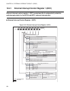
Register Associated with Interrupt Generation by External Interrupt Circuit 1 and
Vector Table
For interrupt operation, see Section "3.4.2 Steps in the Interrupt Operation ".
■
Exercise Caution when Changing Edge Polarity Selection
When changing edge polarity for INT10 to INT12, always write "0" for the appropriate EIR bit to prevent
unintended interrupt generation.
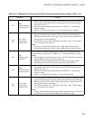
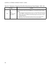
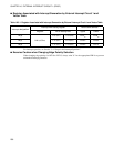
Table 10.5-1 Register Associated with Interrupt Generation by External Interrupt Circuit 1 and Vector Table
Interrupt designation
Interrupt level setting register Vector table address
Register Bit for setting level Upper Lower
IRQ0
ILR1 (007B
H
)
L01 (bit1) L00 (bit0) FFFA
H
FFFB
H
IRQ1 L11 (bit3) L10 (bit2) FFF8
H
FFF9
H
IRQ2 L21 (bit5) L20 (bit4) FFF6
H
FFF7
H