


175
CHAPTER 8 8/16-BIT CAPTURE TIMER/COUNTER
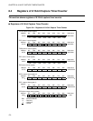
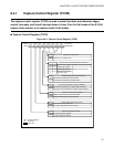
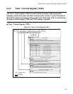
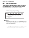
8.4.3 Timer 1 Control Register (TCR1)
The timer 1 control register (TCR1) is used to select functions, allow and prohibit
operation, control interrupts, and check interrupt states in timer 1 for the 8-bit mode of
the 8/16-bit capture timer/counter. When used in the 16-bit mode, TCR1 is controlled by
the timer 0 control register (TCR0), but TCR1 setting is required.
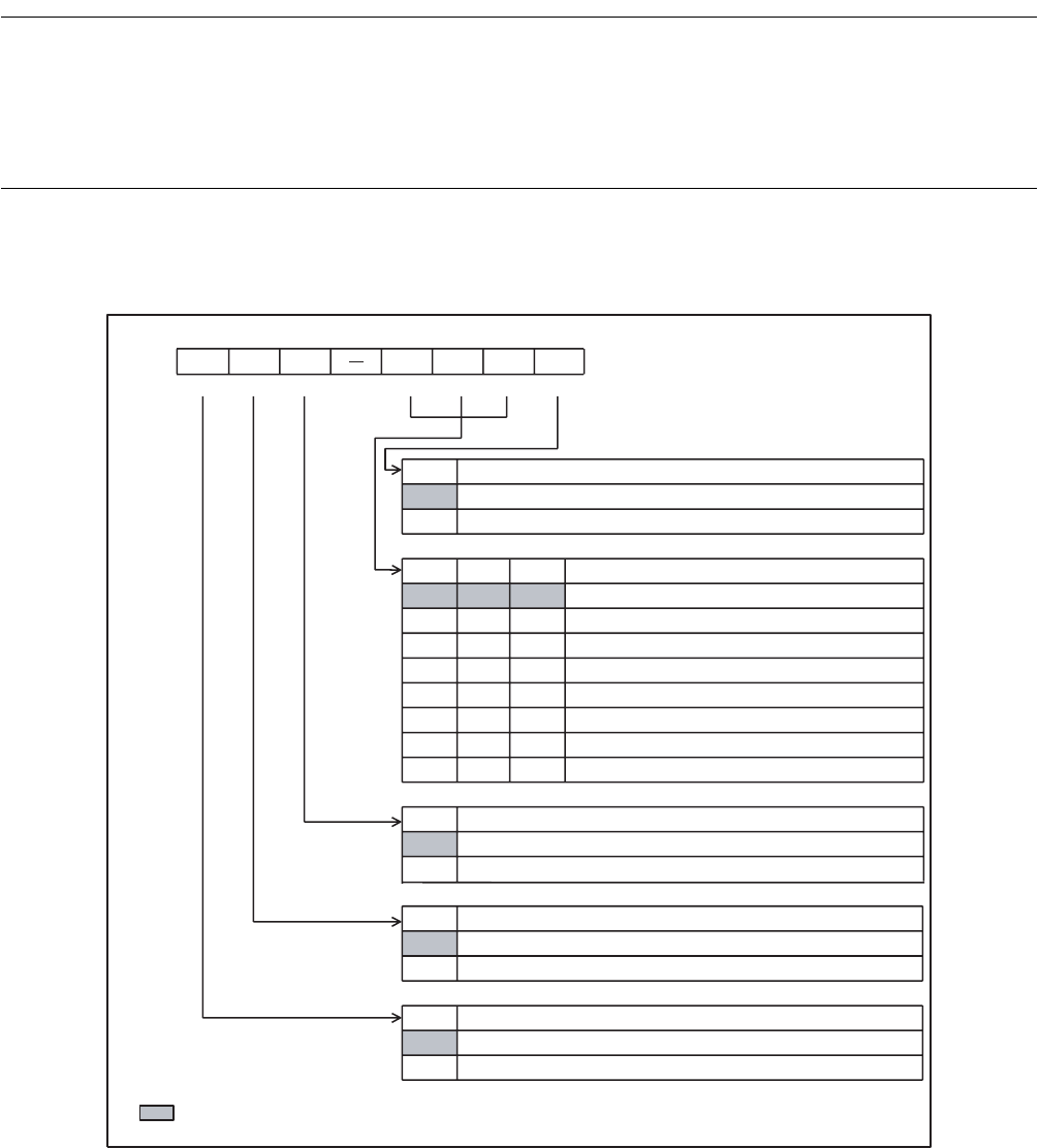
■ Timer 1 Control Register (TCR1)
Figure 8.4-4 Timer 1 Control Register (TCR1)
4t
INST
[1.28 µs]
TSTR1
0
TCS12 TCS11
TCS10
000
001
010
011
100
101
110
111
T1IEN
0
1
TFCR1
0
TIF1
0
bit7 bit6 bit5 bit4 bit3bit2 bit1 bit0
TIF1
TFCR1 T1IEN
TCS12 TCS11
TCS10 TSTR1
R R/W R/W R/W R/W R/W R/W
R/W : Readable/Writable
R : Read only
: Initial value
1
1
1
Address
Initial value
Timer start bit
The counter operation is stopped.
The counter is cleared and increment is started.
Clock source selection bits (oscillation: 12.5 MHz)
16-bit mode
Interrupt request enable bit
Interrupt request output is prohibited.
Interrupt request output is allowed.
Compare match detection flag clear bit
Not affected (at read, always "0")
The compare match detection flag is cleared.
Compare match detection flag bit
A compare match has not occurred.
A compare ma
tch has occurred.
001A
H
2t
INST
[0.64 µs]
16t
INST
[5.12 µs]
64t
INST
[20.48 µs]
128t
INST
[40.96 µs]
256t
INST
[81.92 µs]
512t
INST
[163.84 µs]
000-0000
B
t
INST
: Instruction cycle (Affected by the clock mode and others.)