


402
APPENDIX E Pin State of the MB89202/F202RA Series
APPENDIX E Pin State of the MB89202/F202RA Series
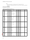
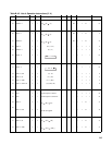
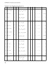
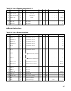
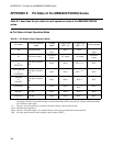
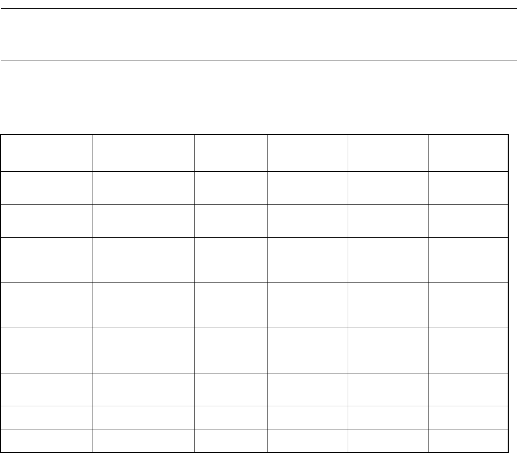
Table E-1 describes the pin states in each operation mode of the MB89202/F202RA
series.
■ Pin States in Each Operation Mode
Table E-1 Pin States in Each Operation Mode
Pin name
In normal operation
mode
In sleep
mode
In stop mode
(SPL = 0)
In stop mode
(SPL = 1)
During a reset
X0 Oscillation input
Oscillation
input
Hi-Z Hi-Z
Oscillation
input
X1 Oscillation output
Oscillation
output
"H" output "H" output
Oscillation
output
P00/INT20/AN4
to
P07/INT27
Port I/O or resource
I/O
Hold Hold
Hi-Z
*1,*2
Hi-Z
P30/UCK/SCK
to
P37/BZ/PPG
Port I/O or resource
I/O
Hold Hold
Hi-Z
*1,*2
Hi-Z
P40/AN0
to
P43/AN3
Port I/O or resource
I/O
Hold Hold
Hi-Z
*2
Hi-Z
P50/PWM
Port I/O or resource
I/O
Hold Hold
Hi-Z
*2
Hi-Z
P60, P61 Port I/O Hold Hold
Hi-Z
*2
Hi-Z
P70 to P72 Port I/O Hold Hold
Hi-Z
*2
Hi-Z
*1: For port input and peripheral input, the internal input level is fixed to prevent them from generating a leak via the
input open. However, if external interrupts are allowed for P00 to P07 and P34 to P36, only the external interrupts
are available as their inputs.
*2: The pins, for which pull-up is selected by the option setting, enter the pull-up state.
Hi-Z: Indicates high impedance.
Hold: The pins, for which output is set, maintain the pin state (level) just before the mode transition.
SPL: Pin state spacification bit of the standby control register (STBC)