


237
CHAPTER 10 EXTERNAL INTERRUPT CIRCUIT 1 (EDGE)
10.5 Interrupt of External Interrupt Circuit 1
The detection of a signal with the specified edge or edges, input to any of the external
interrupt pins, triggers external interrupt circuit 1 to generate an interrupt request.
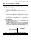
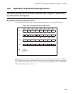
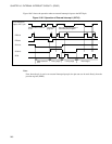
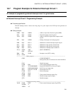
■ Interrupt during the Operation of External Interrupt Circuit 1
When external interrupt circuit 1 detects the specified edge or edges of external interrupt input at a pin, an
external interrupt request flag bit (EIC1, EIC2:EIR0 to EIR2) corresponding to the pin is set to "1". At this
time, if the interrupt request enable bit corresponding to the pin contains the value indicating the enabled
state (EIC1, EIC2:EIE0 to EIE2=1), the external interrupt circuit 1 generates and then issues the
appropriate interrupt request (IRQ0, IRQ1, IRQ2) to the CPU.
Write "0" for the external interrupt request flag bit within the interrupt processing routine for the interrupt
request, thus clearing the interrupt request.
If external interrupts are not used for recovery from stop mode, set the edge polarity selection bits to "00
B
"
and the interrupt enable bits to "0".
Notes:
• When edge detection OFF is selected and set with edge polarity selection bits, the occurring input is
held as is before entry to the internal edge detecting circuit. If edge is selected during the edge detection
OFF state, edge detection may be performed unconditionally with the external interrupt request flag bit
set to "1".
• When interrupts are set enabled (EIC1, EIC2:EIE0 to EIE2=1) after the release from the reset state,
clear the appropriate external interrupt request flag bit (EIR0 to EIR2=0) at the same time.
If the external interrupt request flag bit is "1" with the interrupt request enable bit containing a value
indicating enable state, a return from the interrupt processing is not possible. Always clear the external
interrupt request flag bit within the interrupt processing routine.
• For edge selection during the edge detection OFF state, specify an edge or edges when interrupt request
outputs are disabled and then clear the external interrupt request flag bit.
Regardless of the value of the appropriate interrupt request enable bit (EIE0 to EIE2), the external
interrupt request flag bit is set to "1" whenever edge polarity matching is detected.
Only external interrupt circuits 1 and 2 can execute a release from stop mode by an interrupt.
With the external interrupt request flag bit being set to "1", when the interrupt request enable bit setting
changes from disable to enable (0 → 1), an interrupt request is generated immediately.