


239
CHAPTER 10 EXTERNAL INTERRUPT CIRCUIT 1 (EDGE)
10.6 Operations of External Interrupt Circuit 1
The external interrupt circuit 1 can detect a specified edge or edges of a signal input to
any of the external interrupt pins.
■ Operation of External Interrupt Circuit 1
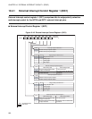
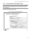
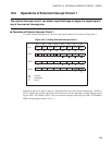
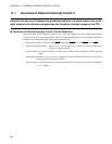
To operate external interrupt circuit 1, the bits of the registers must be set as shown in Figure 10.6-1 .
Figure 10.6-1 Setting External Interrupt Circuit 1
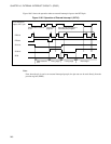
When the polarity of an edge or edges of a signal input from one of the external interrupt pins 1 (INT10 to
INT12) matches the selected edge polarity for the pin stored in the appropriate external interrupt control
register (EIC1, EIC2:SL00 to SL21), one of the external interrupt request flag bits (EIC1, EIC2:EIR0 to
EIR2) corresponding to the pin is set to "1".
bit7 bit6 bit5 bit4 bit3 bit2 bit1 bit0
EIC1 EIR1 SL11 SL10 EIE1 EIR0 SL01 SL00 EIE0
EIC2 EIR2 SL21 SL20 EIE2
DDR3
TCR2 PEN TSEL
0
: Used bit
: Unused bit
0 : Set "0"
000