


277
CHAPTER 12 A/D CONVERTER
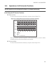
12.8 Program Example for A/D Converter
This section shows a program example of the 10-bit A/D converter.
■ Program Example of the A/D Conversion Functions
● Processing specifications
The analog voltage to be applied to the AN0 pin is converted to digital voltage through software activation.
In this example, completion of conversion is detected in a loop in the program without using interrupts.
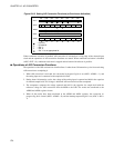
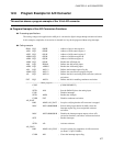
● Coding example
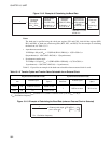
PDR4 EQU 000FH ; Address of port 4 data register 4
ADC1 EQU 0030H ; Address of A/D control register 1
ADC2 EQU 0031H ; Address of A/D control register 2
ADDH EQU 0032H ; Address of A/D data register H
ADDL EQU 0033H ; Address of A/D data register L
ADEN EQU 0034H ; Enables the A/D input pin.
AN0 EQU PDR4:0 ; Defines the AN0 analog input.
ADE0 EQU ADEN:0 ; Enables the AN0 analog input.
ADI EQU ADC1:3 ; Defines the interrupt request flag bit.
ADMV EQU ADC1:2 ; Defines the conversion in-progress flag bit.
AD EQU ADC1:0 ; Defines the bit for activating A/D conversion (software
activation).
EXT EQU ADC2:1 ; Defines the bit for enabling continuous activation.
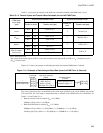
;------------------------Main program--------------------------------------------------------------------------------
CSEG ; [CODE SEGMENT]
:
SETB AN0 ; Sets the P40/AN0 pin to the analog input.
CLRI ; Disables interrupts.
SETB ADE0 ; Enables the AN0 pin.
CLRB EXT ; Disables continuous activation.
AD_WAIT
BBS ADMV,AD_WAIT ; Loop for verifying that the A/D converter is stopped.
MOV ADC1,#00000000B ; Selects analog input channel 0 (AN0), clears the
interrupt request flag, does not perform software
activation.
MOV ADC2,#00000001B ; Disables the interrupt request output, selects A/D
conversion functions, and selects software activation.
SETI ; Enables interrupts.
:
SETB AD ; Activates software.
AD_CONV
BBS ADMV,AD_CONV ; Loop for waiting for completion of A/D conversion
(at about 12.2 µs/12.5 MHz)
CLRB ADI ; Clears the interrupt request flag.