


e-STUDIO3511/4511 CONTROL PANEL 5 - 10 November 2003 © TOSHIBA TEC
5
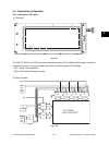
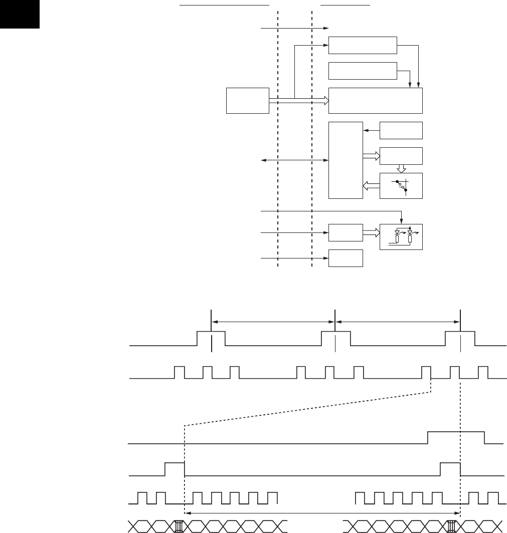
(4) Data Transmission
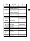
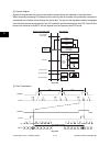
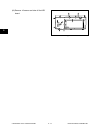
(3) System diagram
Signals flowing between the control panel and the system board are indicated in the chart below.
When the panel processing CPU detects that the control panel is operated, the operational contents are
transmitted to the System board through the serial data. The state of the equipment and the messages
from the System board are received by the LCD controller and then displayed on the LCD. The LED and
buzzers are switched to ON/OFF with the signals from the System control PC board.
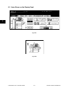
LOAD
FRAME
LOAD
240 1 2 240
CP x(640/4) pulses
12
240
1/tF1/tF
12
FRAME
D0-D3
CP
Fig. 5-403
Fig. 5-404
Inverter for
backlight
Contrast adjustment
circuit
LCD display
640 x 240 dots
LCD
controller
Analog
input
LED driver
Buzzer
Touch panel
Decoder
Hard-key matrix
LED
Buzzer ON signal
LED serial output
Serial data
Power ON/OFF
Reset signals
LED scan signal
Panel
processing
CPU
System control PC board Control panel