


e-STUDIO3511/4511 FUSER UNIT/PAPER EXIT SECTION 16 - 6 November 2003 © TOSHIBA TEC
16
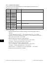
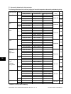
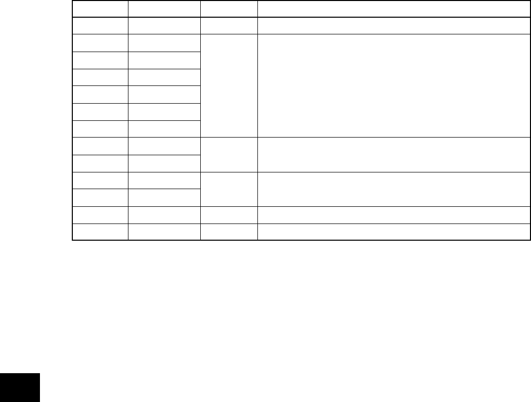
CN No.
CN455-2
CN455-3
CN455-4
CN455-5
CN455-6
CN455-7
CN455-8
CN455-1
CN456-1
CN456-4
CN456-5
CN456-2
CN456-3
Name of single
+5VSW
H1PWR1
H1PWR2
H1PWR3
H2PWR1
H2PWR2
H2PWR3
IH2 ON
IH1 ON
H1ERR1
H1ERR2
SG
IHDUTY
Direction
LGC to IH
LGC to IH
IH to LGC
LGC to IT
Definition
Switching signal of power setting
IH coil energization permitting signal
IH status signal (*Note)
Main/sub switching signal
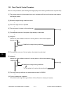
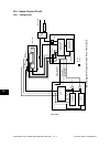
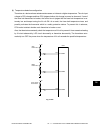
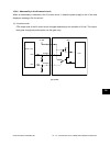
16.4.3 IH control circuit interface
The IH control circuit uses a photocoupler as an insulation against the secondary circuit.
The interface signals are as follows.
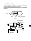
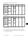
(*Note) IH status signal
• When the temperature (due to insufficient cooling) of the switching element (IGBT) is
abnormal:
“12: Coil is abnormal, IH FAN OFF” → After a certain period of time → Error [C480]
• Main/sub coil continuous energization error (15 sec.): “12: Coil is abnormal, IH FAN OFF” →
After a certain period of time → Error [C480]
• When the upper limit of the power voltage is abnormal:
“10, 11, 14: Initializing” → After a certain period of time → Error [C470]
“07: Ready” → After a certain period of time → Error [C470]
• When the lower limit of the power voltage is abnormal:
“10, 11, 14: Initializing” → After a certain period of time → Error [C470]
“07: Ready” → After a certain period of time → Error [C470]
• Defective circuits →: “13: Abnormal circuit, IH coil abnormality” → Error [C490]
• Ready state after the initialization: “01: Ready”