


e-STUDIO3511/4511 SCANNER 6 - 8 November 2003 © TOSHIBA TEC
6
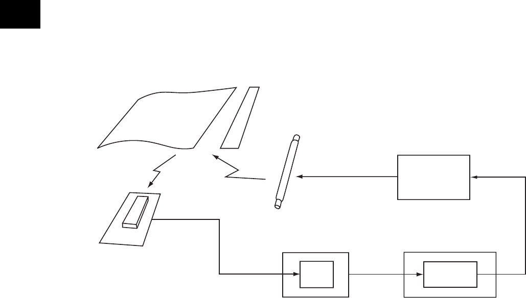
6.4 Control of Exposure Lamp
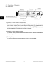
6.4.1 General description
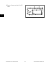
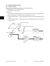
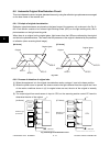
Control circuit for the exposure lamp consists of the following two blocks:
(1) Lighting device for the xenon lamp (Inverter)
Turns ON/OFF the exposure lamp.
(2) CCD circuit
This circuit converts the reflected light amount from the original surface and the shading correction
plate to electrical signals. The exposure amount is controlled in two ways:
(a) White reference formation - reads the reflected light amount from the white shading correction
plate
(b) Black reference formation - reads the light amount at the regulation position with the exposure
lamp lights OFF
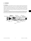
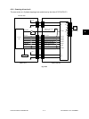
PWA-CCD
PWA-CCD
A/D
PWA-SLG
Fig. 6-401
Original
Shading correction plate
Exposure lamp (Xenon lamp)
CCD
Lighting device
for xenon lamp
(Inverter)
Scanner
CPU