


16
November 2003 © TOSHIBA TEC 16 - 27 e-STUDIO3511/4511 FUSER UNIT/PAPER EXIT SECTION
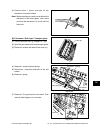
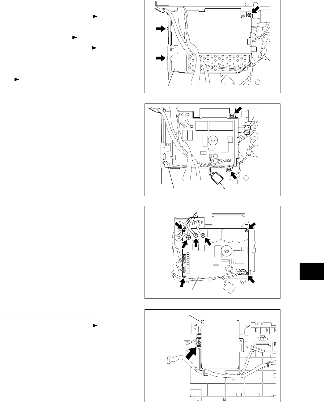
Fig. 16-747
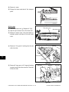
Fig. 16-748
IH board
IH control board
cooling fan cover
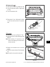
Fig. 16-745
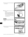
Fig. 16-746
IH board cover
Connector
IH board case
Connector
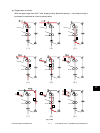
[M] IH control PC board (IH board)
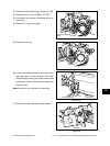
(1) Take off the SYS board case ( Chapter 2.5.2
[C]).
(2) Take off the flywheel ( Chapter 9.5 [A]).
(3) Take off the right rear cover ( Chapter 2.5.1
[L]).
(4) Disconnect 2 connectors and 4 faston terminal
( Chapter 16.7 [A]).
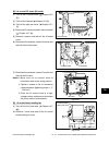
(5) Remove 3 screws and take off the IH board
cover.
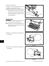
(6) Disconnect 2 connectors, remove 2 screws and
take off the IH board case.
(7) Disconnect 4 connectors, remove 7 screws and
take off the IH board.
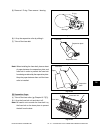
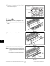
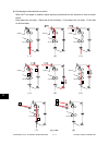
Notes:1.Make sure not to connect each IH
connection cable to the wrong position.
2. Tighten 4 screws of the IH connection
cable completely (tightening torque: 1.17
- 1.56 N·m).
3.Since the IH control board is a high-
voltage section, make sure to disconnect
the power cable at maintenance.
IH connection cable
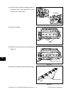
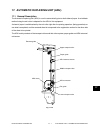
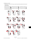
[N] IH control board cooling fan
(1) Take off the IH board case ( Chapter 16.7
[M]).
(2) Remove 1 screw and take off the IH control
board cooling fan cover.