


November 2003 © TOSHIBA TEC 8 - 5 e-STUDIO3511/4511 LASER OPTICAL UNIT
8
(3) f
θθ
θθ
θ
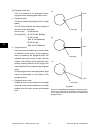
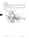
lenses 1 and 2
These two lenses perform the following adjustment on the laser beams reflected by the polygonal
mirror.
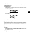
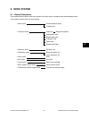
a. Uniform-velocity scanning
Since the polygonal mirror is rotating at a
uniform velocity, the laser beam reflected
from the mirror scans over the drum surface
at a uniform angular velocity; namely, the
pitch between the dots on the drum is wider
at both ends than at the center of the
scanning range. The f
θθ
θθ
θ
lenses help to correct
this difference, making all the dot-to-dot
pitches equal on the drum surface.
b. Face tilt correction
The reflecting face of the polygonal mirror is
tilted slightly to one side against the perfect
vertical. Horizontal deviation of the laser light
which is caused by the tilt is corrected.
c. Sectional shape of laser beam
The shape of the laser beam spotted on the
drum is adjusted.
Wider
Narrower
Drum
f
θθ
θθ
θ
Lens 2
Same intervals
Mirror plane is tilted.
Deviation
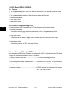
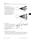
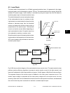
(4) H-Sync signal detection PC board (SNS board)
The laser light which is started to be scanned from one of the reflected plane of the polygonal mirror
is reflected by the H-Sync detection mirror and enters the PIN diode on the H-Sync signal detection
PC board. The primary scanning synchronizing signal is generated based on this reflection.
Fig. 8-203
Fig. 8-204
f
θθ
θθ
θ
Lens 1