November 2003 © TOSHIBA TEC 6 - 19 e-STUDIO3511/4511 SCANNER
6
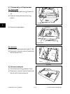
[H] Carriages-1 and -2
(1) Remove the original glass and take off the
upper rear cover ( Chapters 6.7 [A], 2.5.1 [Q]).
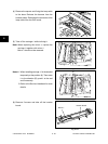
(2) Move the carriage and position the holes of the
carriage to the holes of the frame.
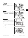
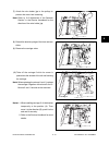
(3) Remove 2 screws and take off the brackets
fixing the carriage-1 to the wire.
Carriage-1
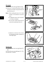
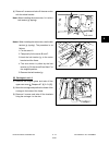
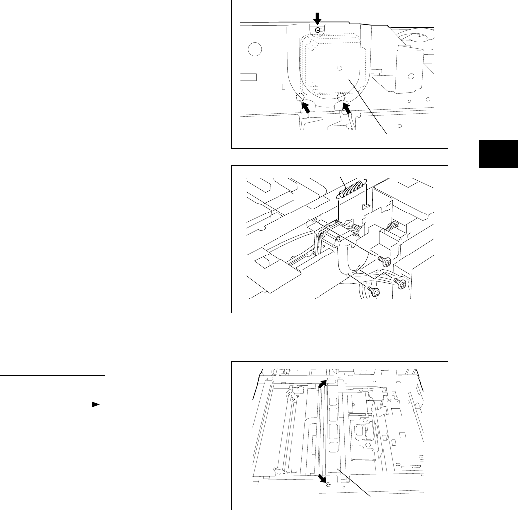
(4) Remove 3 screws and take off the scan motor
with the whole bracket.
Note: When installing the scan motor, fix it with a
belt tension jig (spring).
Scan motor
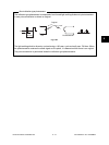
Fig. 6-712
Fig. 6-714
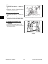
Notes: When installing the scan motor, use the belt
tension jig (spring). The procedure is as
follows.
1. Fix the screw A.
2. Temporarily fix the screw B and C.
3.Hook the belt tension jig to the motor
bracket and the flame.
4.The scan motor is pulled by the belt
tension jig. Fix the screw B and then C at
the stopped position.
5. Remove the belt tension jig.
Fig. 6-713
Belt tension jig
A
B
C
04/05


