November 2003 © TOSHIBA TEC 2 - 33 e-STUDIO3511/4511 OUTLINE OF THE MACHINE
2
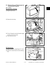
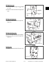
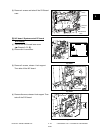
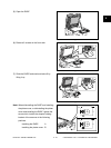
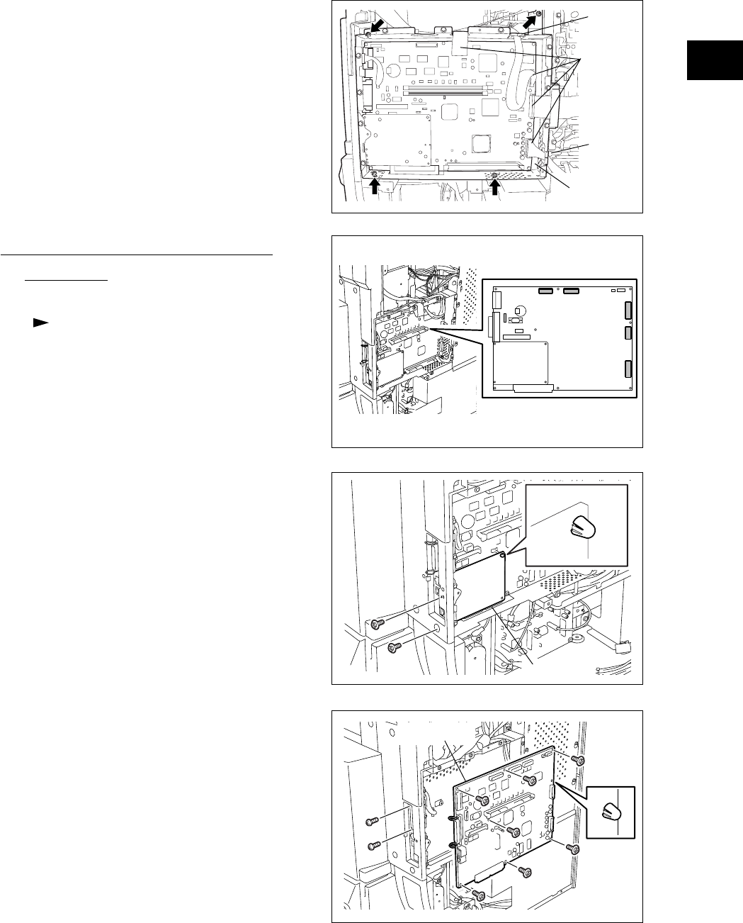
(3) Remove 4 screws and take off the SYS board
case.
Fig. 2-530
SYS board
case
Harness
clamp
Connector
Harness
clamp
[D] NIC board / System control PC board
(SYS board)
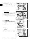
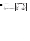
(1) Take off the SYS board lower cover
( Chapter 2.5.2 [B]).
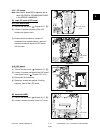
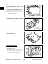
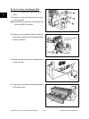
(2) Disconnect 6 connectors.
Fig. 2-531
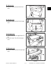
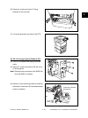
Fig. 2-532
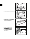
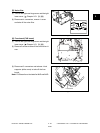
(3) Remove 2 screws, release 1 lock support.
Then take off the NIC board.
NIC board
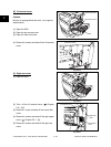
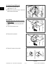
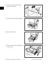
(4) Remove 9 screws, release 1 lock support. Then
take off the SYS board.
Fig. 2-533
SYS board
04/05


