


16
November 2003 © TOSHIBA TEC 16 - 25 e-STUDIO3511/4511 FUSER UNIT/PAPER EXIT SECTION
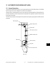
Fig. 16-740
Fig. 16-738
Fig. 16-739
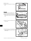
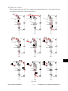
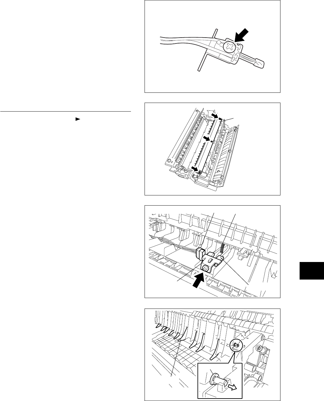
[K] Exit sensor / Exit finger / Transport guide
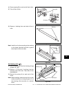
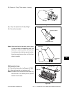
(1) Take off the fuser unit ( Chapter 16.7 [A]).
(2) Open the jam access cover and transport guide.
(3) Remove 3 screws and take off the cover (A).
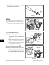
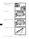
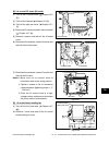
(4) Remove 1 screw and plate spring.
(5) Disconnect 1 connector and take off the exit
sensor.
(6) Remove 1 spring.
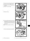
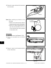
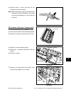
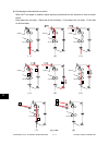
(4) Remove each 1 screw and take off the
thermistor from each bracket.
Note: When installing, be careful not to deform the
thermistor or the frame (plate). Also, make
sure that the thermistor is in touch with the
fuser belt.
Fig. 16-737
Cover (A)
Spring
Connector
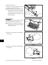
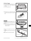
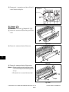
(7) Remove 1 E-ring and pull out the shaft. Then
remove 8 exit fingers and 1 actuator.
Exit sensor
Plate spring
Actuator
E-ring