


e-STUDIO3511/4511 COPY PROCESS 3 - 4 November 2003 © TOSHIBA TEC
3
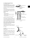
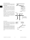
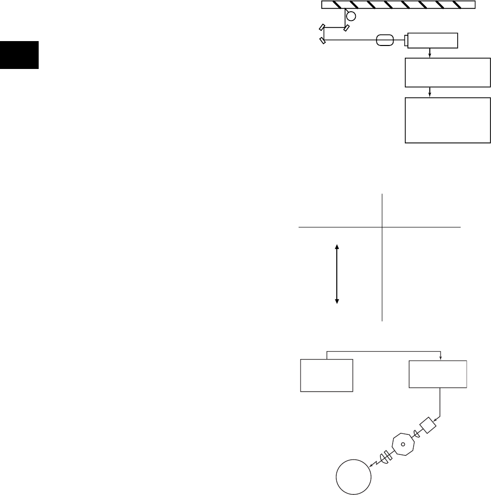
CCD board
Scanning section
control PC board
Image processing
section
(Example)
CCD light
receiving
amount
Value of image
signals to be
output
Light 255
Dark
0
Difference between
"light " and "dark" is
divided into 256 steps.
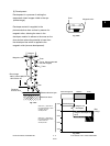
Image
processing
section
Laser driving
PC board
Semiconductor
laser element
Polygonal mirror
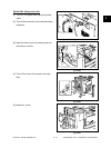
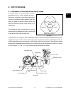
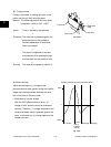
(4) Data writing
Data writing is a process of converting the image
signals transmitted from the image processing
section into light signals and exposing the drum
surface with the light signal.
Namely, the image signals transmitted from the
image processing section are converted into optical
signals (laser emission) by the semiconductor laser
element, which are then used to expose the drum
surface, thus forming an electrostatic latent image
there.
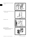
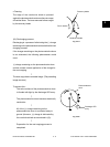
(3) Data reading (scanning)
Data reading is a process of illuminating the original
with light and converting the reflected light into
electrical signals.
The light reflected from the original is directed to
the Charge Coupled Device (CCD) and this optical
image information is converted to electrical signals
(image signals), which are then transmitted to the
image processing section via the scanner control
PC board.
The CCD for color processing has RGB filters
provided over its surface, which allow the CCD to
read the light amount in the respective ranges of
wavelength. The image data corresponding to the
respective RGB colors is then transmitted to the
image processing section.
Drum
Fig. 3-304
Fig. 3-305