


16
e-STUDIO3511/4511 FUSER UNIT/PAPER EXIT SECTION 16 - 18 November 2003 © TOSHIBA TEC
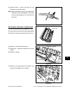
Fig. 16-711
Fig. 16-712
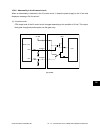
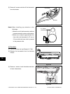
C
S
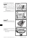
Bracket
Spring
Spring
E-ring
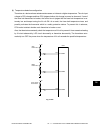
Fig. 16-710
[D] IH coil
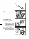
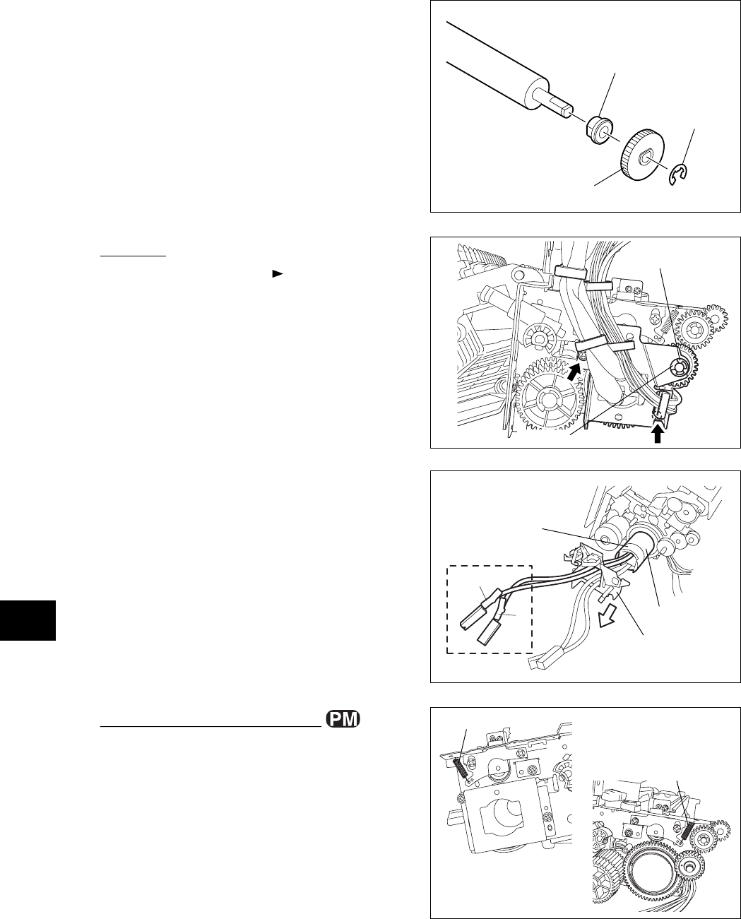
(1) Take off the fuser unit ( Chapter 16.7 [A]).
(2) Release the harnesses from 5 harness clamps.
Then remove 1 E-ring, 1 bushing and 2 screws.
(3) Pull out the bracket and IH coil.
(4) Take out the IH coil from the bracket.
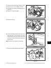
Notes:1.When installing, be sure to set the
harnesses “C” and “S” of 4 harnesses on
upper.
2. Make sure that there is not any scratch
or break on the white tube on the IH coil.
3. Make sure that there is not any peeling
or scratch on the harness tube.
White tube
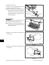
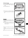
[E] Fuser roller / Fuser belt guide
Note: When installing/disinstalling the fuser roller,
make sure not to remove the spring (shown
in the figure at right) since the removal of
this spring may have the fuser roller press
to deform the thermistor.
- Front side -
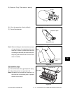
- Rear side -
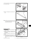
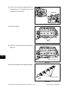
(4) Remove 1 E-ring, the gear (C) and 1 bushing
from the cleaning roller rear side.
Fig. 16-709
Gear (C)
Bushing
E-ring
Bushing
IH coil