e-STUDIO3511/4511 LASER OPTICAL UNIT 8 - 10 November 2003 © TOSHIBA TEC
8
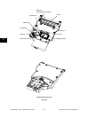
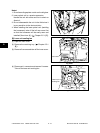
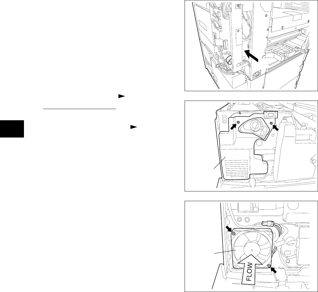
(4) Disconnect 1 connector and remove 2 screws.
Take off the laser unit cooling fan.
Fig. 8-607
Laser unit
cooling fan
Fig. 8-606
[B] Laser unit cooling fan
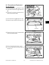
(1) Open the front cover.
(2) Remove the receiving tray ( Chapter 2.5.1
[B]).
(3) Remove 2 screws and take off the inner cover.
Inner cover
Notes:
1. Do not leave fingerprints or stain on the slit glass.
2. Laser optical unit is a precise apparatus.
Handle the unit with extra care not to shock or
vibrate it.
3. Do not disassemble the unit in the field since it
is very sensitive to the dust and stain.
4. When installing the laser optical unit (installing
the harnesses), take off the left rear cover first
so that the harnesses will be easily seen and
installed (View from (A)) ( Chapter 2.5.1 [G]).
Fig. 8-605
(
A
)


