16
e-STUDIO3511/4511 FUSER UNIT/PAPER EXIT SECTION 16 - 24 November 2003 © TOSHIBA TEC
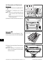
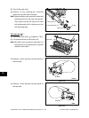
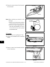
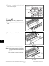
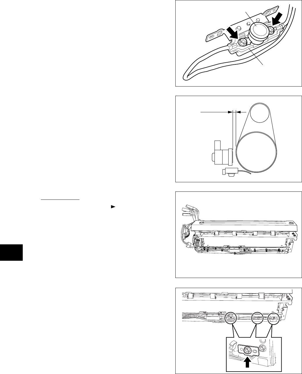
Fig. 16-736
Notes: When installing, pay attention to the
followings:
1. Make sure to fix the thermostat, and then
harness terminal in order on the bracket.
2. Make sure to keep the gap between the
fuser roller and thermostat is 0.7 mm to
2.0 mm while the fuser roller is pressed
to the pressure roller.
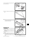
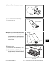
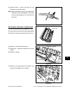
Fig. 16-735
Fig. 16-734
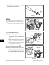
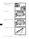
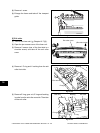
[J] Thermistor
(1) Take off the fuser unit ( Chapter 16.7 [A]).
(2) Release the harnesses from the harness
clamps.
(3) Remove 1 screw of each thermistor and take
off total 3 thermistors.
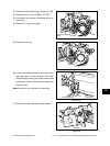
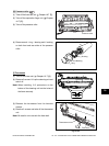
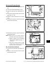
Thermostat
(5) Remove 2 screws and take off the thermostat
from the bracket.
Fig. 16-733
Bracket
0.7-2.0mm


