


e-STUDIO3511/4511 IMAGE PROCESSING 7 - 2 November 2003 © TOSHIBA TEC
7
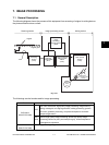
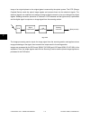
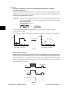
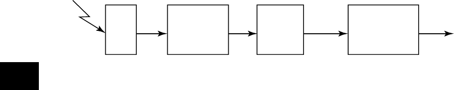
Image of an original placed on the original glass is scanned by the optical system. The CCD (Charge
Coupled Device) reads the optical image signals and converts them into the electrical signals. The
electrical signals are amplified and undergo analog-to-digital conversion, then are changed into digital
signals. Shading correction (correction of variance in CCD elements and the light source) is performed
and the digital signal is output as an image signal from the scanning section.
CCD
A/D
conversion
Shading
correction
Signal
amplification
(Next process)
Fig. 7-102
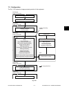
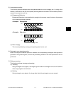
The image processing section inputs the image signal from the scanning section and applies various
image processing on the signal, then transmits the output result to the writing section.
Images are processed by the SYS board (PWA-F-SYS-350) and LGC board (PWA-F-LGC-350) in this
equipment. Also, the image signals read with the Scanning Function and the printer image signals are
processed in the SYS board.