


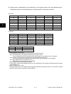
e-STUDIO3511/4511 SCANNER 6 - 18 November 2003 © TOSHIBA TEC
6
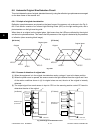
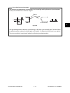
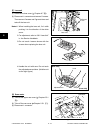
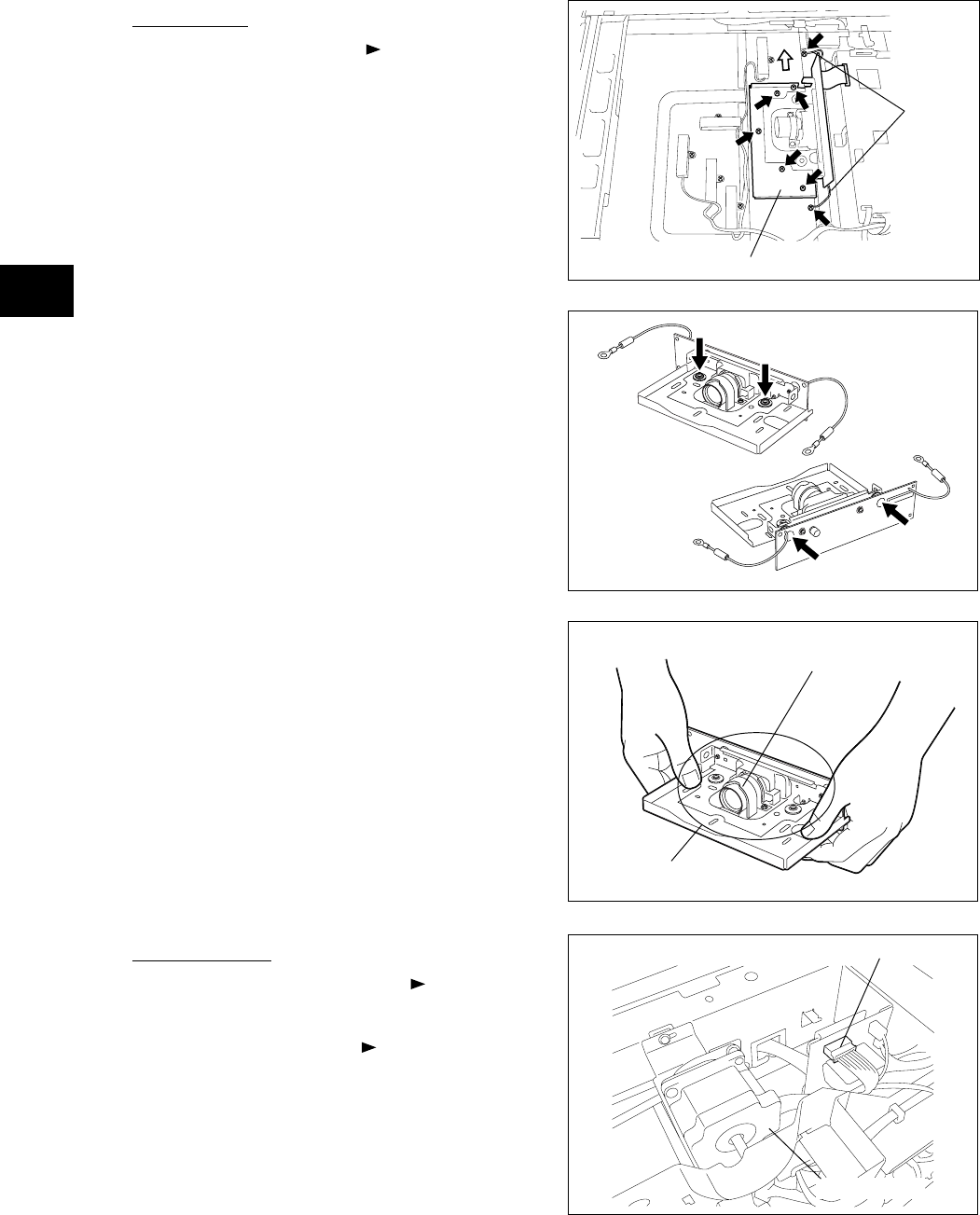
[Rear side]
[Front side]
Lens
Adjusted area
in the Service Handbook.
3. Do not touch 4 screws shown with the
arrows when replacing the lens unit.
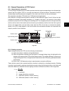
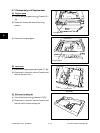
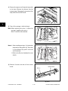
[F] Lens unit
(1) Remove the lens cover ( Chapter 6.7 [B]).
(2) Disconnect 1 connector and remove 5 screws.
Then remove 2 screws and 2 ground wires and
take off the lens unit.
Notes:1. When installing the lens unit, fix it while
pushing it to the direction of the white
arrow.
2. For adjustment, refer to “3.9.2 Lens Unit”
Lens unit
Ground
wire
Fig. 6-708
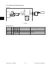
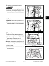
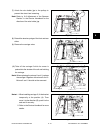
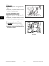
[G] Scan motor
(1) Take off the upper rear cover ( Chapter 2.5.1
[Q]).
(2) Take off the rear cover ( Chapter 2.5.1 [P]).
(3) Disconnect 1 connector.
Connector
Fig. 6-709
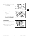
4. Handle the unit with care. Do not touch
the adjusted area and lens. (Hold the unit
as the right figure.)
Fig. 6-710
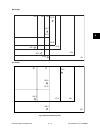
Fig. 6-711
Scan motor