


November 2003 © TOSHIBA TEC 5 - 11 e-STUDIO3511/4511 CONTROL PANEL
5
LDON0
"L"
"L" 17
D7
Q3
IC
R3
(COPY)
5VL
LED
G
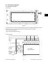
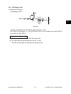
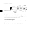
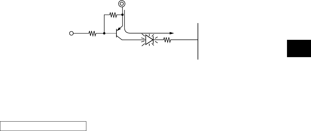
5.4.2 LED display circuit
(1) Method of LED display
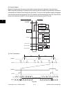
ex) Displaying “COPY” .
Transistor is turned ON when the LDON 0 signal becomes “L” level.
Also, when IC pin changes to “L”, the current flows from 5VL via the transistor to the LED (“COPY”)
to turn ON the LED (“COPY”).
Current
Conditions to turn ON the LED
(a) The transistor (Q3) connected to the LED anode is ON.
(b) The output from the cathode side of the LED is “L” level.
The LED turns ON when the conditions (a) and (b) are met.
Fig. 5-405