


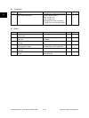


e-STUDIO3511/4511 OUTLINE OF THE MACHINE 2 - 24 November 2003 © TOSHIBA TEC
2
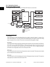
LGC board:
This is the board to mainly control the print function (printer engine). It consists of the Engine-CPU,
ASIC, memory (Flash ROM, SRAM, NVRAM), etc. The Engine-CPU controls each ASIC to drive I/O
(electrical parts) of each section in the system. It leads to the operation of the laser unit, revolver,
developer unit, drum, transfer belt, drawers, bypass unit, ADU, etc. And then the print is made.
NIC board:
This is the interface board to connect this equipment to the LAN environment (10BASE-T, 100BASE-
TX) to communicate with PCs, etc.
FIL board:
This is the board to cut off the noise of AC power from outside, and supply the driving AC power to
the damp heater for condensation prevention of each section (scanner and drum).
FUS board:
This is the board to provide the AC electric power for driving to the damp heater for preventing of the
condensation of each section (scanner and drum).
HVT:
This is the board to generate the DC high voltage from +24V to provide the bias to the section of the
main charger, developer, and transfer.
PS-ACC:
This is the unit to generate each DC voltage, which is used in the equipment, from external AC
electric power input. And then it is provided to each electric part.