


November 2003 © TOSHIBA TEC 9 - 3 e-STUDIO3511/4511 DRIVE SYSTEM
9
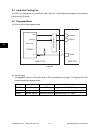
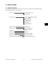
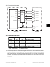
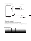
9.2.2 Drive circuit of main motor
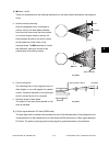
(1) The control signal from LGC controls the operations of the main motor, such as switching of ON/OFF,
a rotational direction, a rotational speed, etc. The rotational speed is decided by clock frequency
output at the main motor. The speed is lowered to the range from 1/2 to 1/4 at the Thick Paper/OHP
Film Mode. This switching is performed between the completion of the 1st transfer and that of the
2nd transfer.
Signal Level “L” Level “H” Remarks
MAMON ON OFF Main motor ON signal
MAMBK Braking Normal Main motor brake signal
MAMCW CW CCW Main motor rotational direction signal
MAMGA Low speed High speed Main motor speed switching signal
MAMCK — — Main motor reference clock signal
MAMPL Normal Out of control Main motor PLL signal
* CCW: forward rotation CW: backward rotation
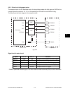
7407
62385
MAMON
MAMCW
MAMBK
MAMPL
PWA-F-LGC Main Motor
MAMCK
MAMGA
PK0
PK2
PK1
DCCLK1
PK3
Gate array
Fig. 9-202
9.2.3 Signal level of motor circuit