


e-STUDIO3511/4511 DRUM RELATED SECTION 11 - 8 November 2003 © TOSHIBA TEC
11
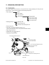
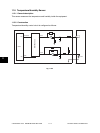
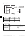
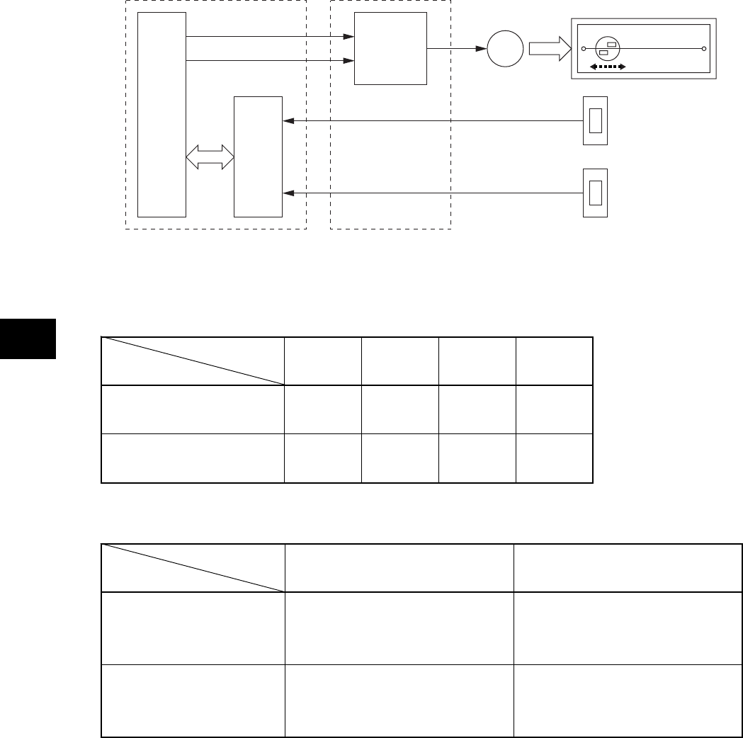
11.6.3 Drive circuit
The circuit configuration is as shown below.
Fig. 11-601
Signal level of motor circuit
Signal level of switching circuit
Signal
ENVMT1-0
Wire cleaner drive signal-1
ENVMT2-0
Wire cleaner drive signal-2
OFF
L
L
Reverse
rotation
L
H
Normal
rotation
H
L
Brake
H
H
Signal
ENVSNR1-0
Charger wire cleaner front
position detection signal
ENVSNR2-0
Charger wire cleaner rear
position detection signal
L
Charger wire cleaner is at the front
position
Charger wire cleaner is at the rear
position
H
Charger wire cleaner is at the
position other than the front
position
Charger wire cleaner is at the
position other than the rear
position
Motor
Level
LGC board PWA-CCL
CPU
Driver
ASIC
GA
ENVMT1-0
ENVMT2-0
ENVSNR1-0
ENVSNR2-0
M