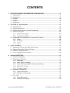
e-STUDIO3511/4511 CONTENTS ii November 2003 © TOSHIBA TEC
5. CONTROL PANEL ........................................................................................................ 5-1
5.1 Control Panel and Display Panel ....................................................................................... 5-1
5.2 Items Shown on the Display Panel .................................................................................... 5-2
5.2.1 Display .................................................................................................................... 5-3
5.3 Relation between the Equipment State and Operator’s Operation .................................... 5-8
5.4 Description of Operation .................................................................................................... 5-9
5.4.1 Dot matrix LCD circuit ............................................................................................. 5-9
5.4.2 LED display circuit ................................................................................................ 5-11
5.5 Disassembly and Replacement........................................................................................ 5-12
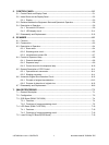
6. SCANNER ..................................................................................................................... 6-1
6.1 Function ............................................................................................................................. 6-1
6.2 Construction ....................................................................................................................... 6-2
6.3 Description of Operation .................................................................................................... 6-4
6.3.1 Scan motor ............................................................................................................. 6-4
6.3.2 Scanning drive circuit .............................................................................................. 6-5
6.3.3 Initialization at power-ON ........................................................................................ 6-7
6.4 Control of Exposure Lamp ................................................................................................. 6-8
6.4.1 General description ................................................................................................. 6-8
6.4.2 Exposure lamp ........................................................................................................ 6-9
6.4.3 Control circuit for the exposure lamp .................................................................... 6-10
6.5 General Description of CCD Control ................................................................................ 6-11
6.5.1 Opto-electronic conversion ................................................................................... 6-11
6.5.2 Shading correction ................................................................................................ 6-11
6.6 Automatic Original Size Detection Circuit......................................................................... 6-12
6.6.1 Principle of original size detection ......................................................................... 6-12
6.6.2 Process of detection of original size ..................................................................... 6-12
6.7 Disassembly and Replacement........................................................................................ 6-16
7. IMAGE PROCESSING .................................................................................................. 7-1
7.1 General Description ........................................................................................................... 7-1
7.2 Configuration...................................................................................................................... 7-3
7.3 SYS Board (PWA-F-SYS-350) ........................................................................................... 7-4
7.3.1 Features .................................................................................................................. 7-4
7.3.2 Functions of image processing circuit ..................................................................... 7-5
7.4 LGC Board (PWA-F-LGC-350) ........................................................................................ 7-10
7.4.1 Features ................................................................................................................ 7-10
7.4.2 Functions of image processing circuit ................................................................... 7-10
7.5 Laser Driving PC Board (LDR Board) .............................................................................. 7-10


