


November 2003 © TOSHIBA TEC 16 - 15 e-STUDIO3511/4511 FUSER UNIT/PAPER EXIT SECTION
16
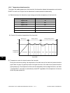
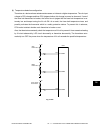
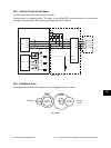
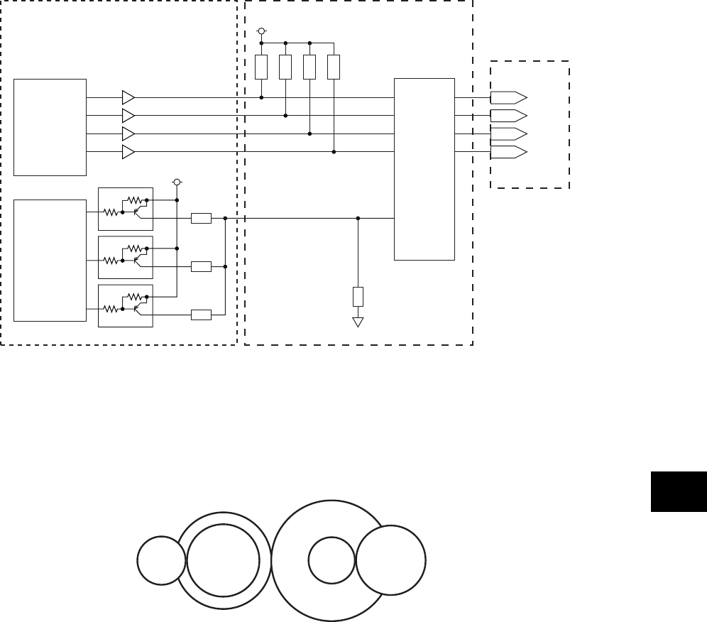
16.5 Control Circuit of Exit Motor
The following is the control circuit of the exit motor.
The exit motor is a stepping motor. The motor is turned ON/OFF and the direction of its rotation is
switched by controlling the output timing of pulse signal (A0·A1·B0·B1).
G14
G22
G24
G20
G48
G16
Exit roller
(
φ
15)
Exit motor
PG10
PG12
PG11
PG13
CPU
EXTMA
EXTMB
EXTMC
Exit Motor
EXTMD
EXTMA-0
+5V
EXTMB-0
EXTMC-0
EXTMD-0
STK672
A
AB
B
BB
A1
B1
A0
B0
VREF
PG0
PG1LCA301
PG2
5V SW
LGC DRV
Fig. 16-501
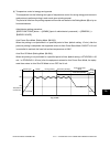
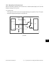
16.6 Exit Motor Drive
The diagram shown below is the layout of the driving gears of the exit roller.
Fig. 16-601