


November 2003 © TOSHIBA TEC 12 - 7 e-STUDIO3511/4511 DEVELOPER UNIT
12
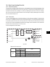
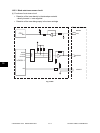
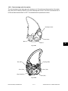
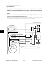
Magnetic resistance
Drive
winding
Detection
winding
DC
conversion
circuit
(Developer material)
Magnetic circuit
Auto-toner output
Main CPU
(LGC board)
V
ATS
Fig. 12-504
(2) Functions of the black auto-toner sensor
a. Initializing function: When unpacking and replacing the developer material
The automatic adjustment is made so that the output of the auto-toner sensor (input value of the
main CPU) will be 2.45V to 2.55V for the toner density of new developer material.
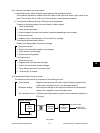
b. Toner density stabilizing function: During the printing operation
Through the following phases, the toner density is kept constant.
Toner is consumed.
→ Toner density decreases.
→ Output change of the auto-toner sensor is detected depending on the humidity.
→ Drives toner motor.
→ Supplies toner to the developer unit from the toner cartridge.
c. Toner-empty detection/clear function:
Detects toner being empty in the toner cartridge.
Drives toner motor.
→ Output of the auto-toner sensor is not changed.
→ Toner density is not changed.
→ Detects toner being empty.
Toner-empty clear
Drives toner motor.
→ Supplies toner from the toner cartridge.
→ Output of the auto-toner sensor changes.
→ Toner density recovers to its normal value.
→ “Toner-empty” is cleared.
(3) Operations of black auto-toner sensor
The black auto-toner sensor is composed of the following circuits.
Drive winding : Magnetic head (primary side) with a high-frequency magnetic field,
which forms a magnetic circuit in the developer material
Detection winding : Receiving the changes in the magnetic resistance of the developer
material via a magnetic circuit (secondary side)
DC conversion circuit : Converting the high-frequency output from the detection winding to a
DC signal