


e-STUDIO3511/4511 IMAGE QUALITY CONTROL 15 - 2 November 2003 © TOSHIBA TEC
15
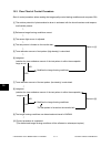
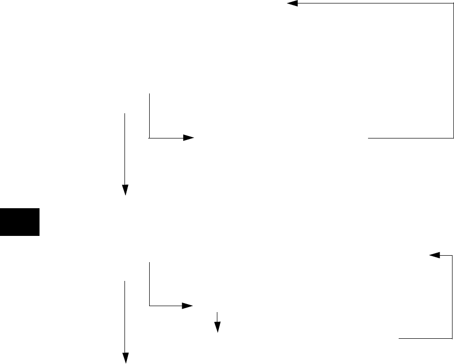
15.3 Flow Chart of Control Procedure
Start of control procedure (when meeting the image quality control starting conditions such as power-ON)
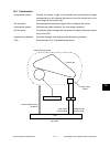
[1] The surface potential of photoconductive drum is estimated with the drum thermistor and tempera-
ture/humidity sensor.
[2] Reference image forming conditions are set.
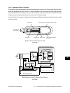
[3] The sensor light source is adjusted.
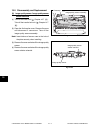
[4] The test pattern is formed on the transfer belt.
[5] Toner adhesion amount of test pattern (high density) is calculated.
[6] Judgment
(whether the toner adhesion amount of the test pattern is within the acceptable
range or not)
NO
Modifies the image forming conditions.
YES
[7] Toner adhesion amount of the test pattern (low density) is calculated.
[8] Judgment
(whether the toner adhesion amount of the test pattern is within the acceptable
range or not)
NO Return to [8].
Modifies the image forming conditions.
YES
The test pattern is formed on the transfer belt.
[9] The image forming conditions are determined and stored in NVRAM.
[10] Control procedure is completed.
(The determined image forming conditions will be reflected on subsequent copies.)
Return to [4].
→→→→→
→→