


November 2003 © TOSHIBA TEC 6 - 1 e-STUDIO3511/4511 SCANNER
6
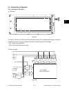
6. SCANNER
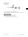
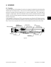
6.1 Function
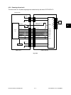
In the scanning section of this equipment, the surface of an original is irradiated with a direct light and the
reflected light is led through mirrors, a lens and a slit to CCD where optical-to-electrical conversion is
performed, converting the optical image data into an electrical (analog) signal. This analog signal is
changed to a digital signal, which then undertakes various corrective processes necessary for image
formation. After that, arithmetic operation is performed on the digital signal, which is then transmitted to
the data writing section.
In this equipment, a reduction-type CCD for color processing is used. What this CCD differs from black-
and-white CCDs is that its devices are arranged in 4 lines and covered with color filters (Red, Green, and
Blue). These lines are composed with 3-line color devices and black-and-white device with no filter.
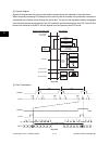
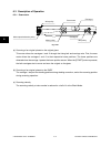
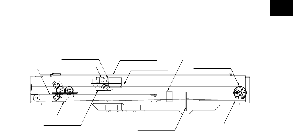
Rail for carriage-2
Reflector
Exposure lamp
Original glass
Rail for carriage-1
Lens
Drive pulley
SLG board
CCD board
Carriage-1
Carriage-2
Fig. 6-101