


November 2003 © TOSHIBA TEC 2 - 31 e-STUDIO3511/4511 OUTLINE OF THE MACHINE
2
2.5.2 PC boards
Note: When the PC board/HDD is replaced, refer to
each CAUTIONS of TROUBLESHOOTHING
in the SERVICE HANDBOOK.
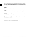
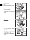
[A] Logic PC board (LGC board)
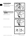
(A-1) LGC board case
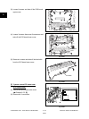
(1) Take off the rear cover ( Chapter 2.5.1 [P]).
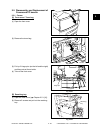
(2) Loosen 13 screws and take off the LGC
board cover (plate cover).
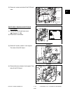
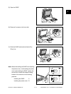
(3) Disconnect 20 connectors, release 12
harnesses from harness clamps, remove 5
screws and take off the whole LGC board
with the case.
Fig. 2-522
Fig. 2-523
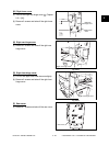
LGC board
cover
LGC board
case
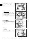
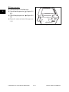
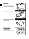
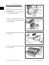
(A-2) LGC board
(1) Take off the rear cover ( Chapter 2.5.1 [P]).
(2) Loosen 13 screws and take off the LGC board
cover (plate cover) ( Chapter 2.5.2 (A-1).
(3) Disconnect 20 connectors.
(4) Remove 4 screws and release 2 locking
supports, take off the LGC board.
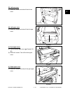
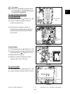
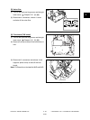
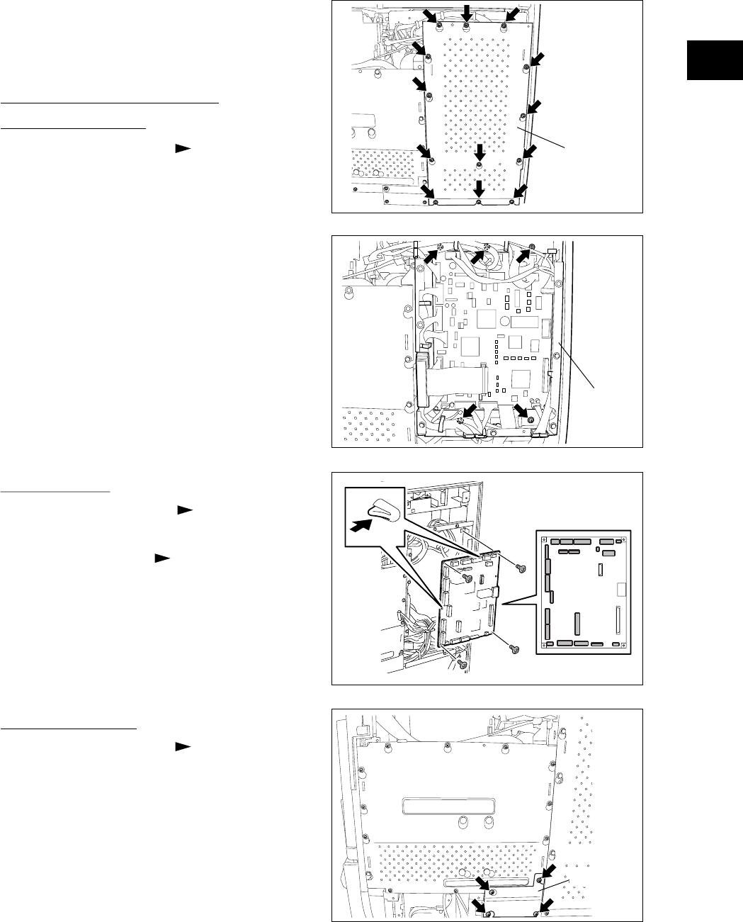
[B] Hard disk (HDD)
(1) Take off the rear cover ( Chapter 2.5.1 [P]).
(2) Loosen 4 screws and take off the HVT cover.
Fig. 2-525
HVT cover
Fig. 2-524
04/05