


November 2003 © TOSHIBA TEC 18 - 1 e-STUDIO3511/4511 POWER SUPPLY UNIT
18
18. POWER SUPPLY UNIT
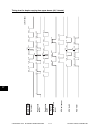
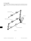
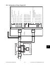
18.1 Construction
The power supply unit consists of an AC filter and insulation type DC output circuits.
(1) AC filter
Eliminates noise from the outside and prevents the noise generated by the equipment from leaking to
the outside.
(2) DC output circuits
Converts AC voltage input from outside to DC voltage and supplies it to each electric part. The DC
voltage is divided into the following two lines.
a. Main line : Power supply used in the entire equipment during image forming process. Four
kinds of voltage (+3.3V, +5.1V, +12V and –12V) are output when the main switch of
the equipment is turned ON.
b. Door switch line : Power supply used in the entire equipment during image forming process, being
supplied via the door switch. Two kinds of voltage (+5.1VD and +24VD) are output
only when the main switch of the equipment is turned ON and two doors (front cover
and jam access cover) are closed.
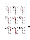
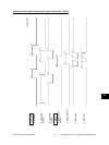
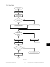
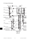
18.2 Operation of DC Output Circuits
(1) Starting line output
When the main switch of the equipment is turned ON, power starts supplying to all the lines only when
two doors (front cover and jam access cover) are closed.
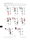
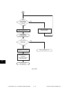
(2) Stopping line output
When the main switch of the equipment is turned OFF, PWR-DN signal is output after the instantaneous
outage insurance time (20 ms or more) elapses and then the supply of each voltage stops. If the supply
of voltage of the main line (+3.3VA, +5.1VA, +12VA, -12VA) stops earlier than the 24V line does, it may
cause the damage of the electron device on each control circuit. To prevent this, the supply of these
voltages stops after the PWR-DN signal is output and the minimum retaining time (+3.3VA/+5.1VA: 50
ms or more, +12VA/-12VA: 5 ms or more) elapses.
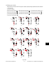
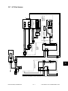
(3) Output protection
Each output system includes an overcurrent and overvoltage protection circuits (a fuse and internal
protection circuit). This is to prevent the defectives (damage or abnormal operation of the secondary
circuit) which may be caused by an overcurrent due to a short circuit or an overvoltage due to a short
circuit between different voltages. If the protection circuit is activated (except the case the fuse is blown
out), remove the causes such as short-circuit. Turn ON the power again 1 minute later to clear the over-
current protection.