276 Encore Presentation System • User’s Guide • Rev 04
6. System Setup
Input Patching
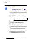
Use the following steps to patch inputs to specific source buttons:
1. In the System Keypad, press SYSTEM to display the System Menu.
2. Press {INPUT PATCH} to display the Input Source Patch Menu.
3. On the Source Number line, select the source button on the Controller that you
want to patch.
4. (Optional) If required, press {DELETE PATCH} to clear all registers for a selected
source button. This enables you to start again with an “undefined” patch.
5. On the Connection Type line, select the router, ScreenPRO-II or the physical
connector that you want the selected button to communicate with. Four options
are available:
~ Select a router by name (e.g., MatrixPRO1).
~ Select a DIRECT SDI, Analog or DVI connection.
~ Select an individual ScreenPRO-II ID (e.g., SP 9).
~ Select ALL SP. This selection assumes connections from D/As to similar
inputs on all ScreenPRO-IIs in your system.
6. If you selected a router:
a. On the Router Input line, select the physical router input that you wish to
associate with the source button.
b. Continue with step 10.
7. If you selected a DIRECT connection:
a. On the ID line, choose the ID of the Video Processor or ScreenPRO-II
that you want to address.
b. Select the input to which the source is physically connected:
• If you chose the ID of a
Video Processor, on the VP Input line,
select the specific M/E input connector on the Processor
• If you chose the ID of a
ScreenPRO-II, on the SP Input line,
select the specific input connector on the ScreenPRO-II.
c. Continue with step 10.
8. If you selected an individual ScreenPRO-II ID:
a. On the SP Input line, select the specific input connector on the
ScreenPRO-II.
b. Continue with step 10.
9. If you selected ALL SP:
a. On the ScreenPRO-II Input line, select the “common” input connector
on all ScreenPRO-IIs to which the sources are physically connected.
b. Continue with step 10.
10. On the Tally Number line, select the tally that you want to associate with the
source button. (If tallies are not connected, in Appendix A, refer to the “
Tally
Connector” section on page 374 for pinout details.)
11. Press {ADD PATCH} to confirm your changes.
12. Repeat the procedure from step 3 to patch additional Controller buttons.
13. Press {BACK} to return to the System Menu.
14. In the System Keypad, press SAVE to save the new configuration in memory.


