


Encore Presentation System • User’s Guide • Rev 04 87
3. Hardware Installation
Installation
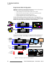
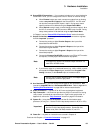
b. On the second stack:
• Connect the bottom stack’s
DVI Preview Output to the top
stack’s Background 1 input (
3A).
• Connect the bottom stack’s
DVI Program Output to the top
stack’s Background 2 input (
3B).
8. D/A Connections —
a.
If your system includes analog, SDI or DVI D/As, connect video inputs to
the D/As as required.
b. Connect D/A outputs to the to the desired M/E input connectors on the
first stack only.
9. Router Connections — if you elect to use router connections, in place of (or in
addition to) direct connections:
a. For Ethernet controlled routers, ensure that they are connected to the
same Switch as the Controller and processors. Ensure that each router
has an unique IP address.
b. To connect a single serial controlled router, use an RS-232 cable to
connect the router to the Controller’s
EXT COMM port. In Chapter 2,
refer to the “
Controller Rear Panels” section on page 58 for details.
c. To connect two (or more) serial routers, a third-party Ethernet-to-Serial
converter is required, such as the
Lantronix model UDS100, UDS200 or
UDS2100 (http://www.lantronix.com). Each UDS2100 can control two
serial routers.
• Using RS-232 cables, connect each router to the
UDS2100.
• Set up a static IP address on the Lantronix. The recommended
range is
192.168.0.191 - 192.168.0.240 — so as not to conflict
with other devices.
• Using an Ethernet cable, connect the
UDS2100 to the same
Ethernet Switch as the Controller and processors.
d. Ensure that all sources are connected to your router(s).
e. Connect all selected router outputs to the desired M/E inputs on the first
stack only:
• For PIPs 1 - 6, connect router outputs to the desired M/E inputs
on the “
bottom stack” processor.
• For PIPs 7 - 12, connect router outputs to the desired M/E
inputs on the “
top stack” processor.
f. If your configuration includes one (or more) destination ScreenPRO-II
units, connect two outputs from each router to each ScreenPRO-II.
10. ScreenPRO-II Connections — if your system includes one (or more) destination
ScreenPRO-II units, you can configure them for internal or external routing:
a. When External routers are used, connect two outputs from an Analog
router to
any two HD-15 inputs on ScreenPRO-II. An SDI router can
also be connected to BNC inputs
1 and 2. During setup, these specific
patches will be defined using the
Output Patch Menu.
b. When Internal routing is used, connect Analog sources to inputs 1 - 8 on
the HD-15 connectors, and SDI sources to BNC inputs
1 and 2. During
setup, these patches will be defined using the
Input Patch Menu.
In Chapter 6, see the “
ScreenPRO-II Destination Setup” section for details.