


Encore Presentation System • User’s Guide • Rev 04 91
3. Hardware Installation
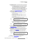
Connection Charts
p~ãéäÉ=`çååÉÅíáçå=`Ü~êíë
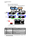
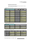
Following are sample connection charts for an Encore system comprised of 1 x analog
router, 2 x direct inputs, and 6 x destinations.
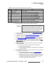
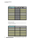
Table 3-8. Router I/O Chart #1 (sample)
Router #1 Router Type: x Analog Digital DVI
Source Name Encore Input # Router Input/Output Connects to:
DVD A 1 / 33 1 VP 1 - 1A
DVD B 2 / 34 2 VP 1 - 1B
Flash CPU 3
3 VP 1 - 2A
4 VP 1 - 2B
Multi A 4
5 VP 1 - 3A
Multi B 5 6 VP 1 - 3B
Multi C 6
7 ScreenPRO 5 - In 1
Multi D 7 / 39 8 ScreenPRO 5 - In 2
Key Dell 1 8
9 VP 3 - 2A
Key Dell 2 9 10 VP 3 - 2B
11 VP 3 - 3A
12 VP 3 - 3B
ImagePRO 2 13
13
ImagePRO 1 14 14 ImagePRO 2 - In 3
ScreenPRO 2 Preview 15
15 ImagePRO 1 - In 2
BEM CPU 16 16 Bottom LC40
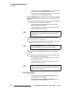
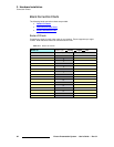
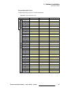
Table 3-9. Direct Encore Input Chart (sample)
Direct Encore Inputs
Source Name Encore Input # Video Processor Encore Port
Comp 1 59 1 1A, DVI
Comp 2 60 1 1B, DVI
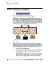
Table 3-10. Encore Destination Chart (sample)
Destination Device Screen Notes
Controller SC
1 VP 1, VP 2 FLM Wide DVI to FLM L and R
2 VP 3 XLM Single DVI to XLM
3 VP 4 LC 40 Top Pvw / Pgm Monitor
4 ImagePRO 1 Any A-14, HD-16, D-1
5 SP 5 FLM Single
6 Router Aux 12 Downstage Mon