


66 Encore Presentation System • User’s Guide • Rev 04
3. Hardware Installation
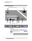
Installation
2. In Appendix A, refer to the “Physical and Electrical Specifications” section on
page 367 for electrical and mechanical details.
3. In Chapter 2, refer to the “Video Processor Rear Panel” section on page 45 and
the “
Controller Rear Panels” section on page 58 for all connector locations.
4. For the VP, follow the rack mount procedures as outlined in the “Rack-Mount
Installation” section on page 62.
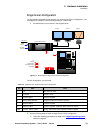
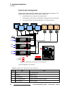
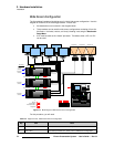
5. Ethernet Connections — a totally “local” network connection is recommended.
Using Ethernet cables:
a. Connect the VP and Controller to the Ethernet Switch, then connect
router(s) to the Switch.
b. As required, connect ScreenPRO-II, PresentationPRO-II and ImagePRO
systems to the Switch.
6. Direct Source Connections — if you elect to use direct connections in place of
(or in addition to) router connections:
a. As an important prerequisite, complete your “Connection Charts” on
page 89 to streamline your source installation procedure.
b. Using the information from the chart, connect the desired “direct”
sources to each M/E’s input connectors as required.
c. As required, connect unscaled background and DSK sources, as
provided from a PC’s single head graphics card.
7. D/A Connections —
a. If your system includes analog, SDI or DVI D/As, connect video inputs to
the D/As as required.
b. Connect D/A outputs to the to the desired M/E input connectors.
8. Router Connections — if you elect to use router connections in place of (or in
addition to) direct connections:
a. For Ethernet controlled routers, ensure that the router(s) are connected
to the same Ethernet Switch as the Controller and Processor. Ensure
that each router has a unique IP address.
b. To connect a single serial controlled router, use an RS-232 cable to
connect the router to the Controller’s
EXT COMM port. In Chapter 2,
refer to the “
Controller Rear Panels” section on page 58 for details.
c. To connect two (or more) serial routers, a third-party Ethernet-to-Serial
converter is required, such as the
Lantronix model UDS100, UDS200 or
UDS2100 (http://www.lantronix.com). Each UDS2100 can control two
serial routers.
• Using RS-232 cables, connect each router to the
UDS2100.
• Set up a static IP address on the Lantronix. The recommended
range is
192.168.0.191 - 192.168.0.240 — so as not to conflict
with Encore devices. See the
Lantronix User’s Guide.
• Using an Ethernet cable, connect the
UDS2100 to the same
Ethernet Switch as the Controller and Processor(s).
Note
A VPx can only be used in a single processor configuration in
the special widescreen “preview” mode. Refer to the “
Wide
Screen Configuration Plus Wide Screen Preview” section
on page 76 for details.