


Encore Presentation System • User’s Guide • Rev 04 55
2. Hardware Orientation
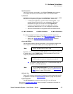
Video Processors
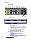
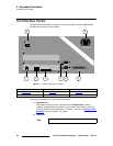
b) Source Link Out
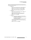
One DVI connector is provided for the M/E’s Source Link Output. For wide
screen and multi-screen applications, this connector loops your inputs to the
next
VP or VPx in the chain. Because all analog and digital inputs reside in the digital
domain, each “link” output loops those inputs to the next Processor’s scalers.
An M/E’s
Source Link Output must always be connected to its associated M/E
Source Link Input on the next chassis, and never cross-routed.
Please note:
~ In a multi-chassis configuration, the link can extend to all chassis.
~ In all cases, the looped inputs are “pre-scaler.”
In Chapter 3, refer to the “
Program and Source Link Connections” section on
page 98 for details on proper connector usage in wide screen configurations.
In Appendix A, refer to the “
DVI Connector Pinouts” section on page 369 for
pinout details.
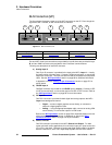
c) Source Link In
One DVI connector is provided for the M/E’s Source Link Input. For wide screen
and multi-screen applications, this connector accepts the looped outputs from the
previous VP or VPx in the chain. An M/E’s
Source Link Input must always be
connected to its associated M/E
Source Link Output on the previous chassis,
and never cross-routed.
In Chapter 3, refer to the “
Program and Source Link Connections” section on
page 98 for details on proper connector usage in wide screen configurations.
In Appendix A, refer to the “
DVI Connector Pinouts” section on page 369 for
pinout details.
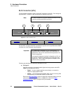
d) DVI Input B
One DVI-I connector is provided for both digital and analog inputs to the M/E’s
Layer B and background channel.
~ Digital — connect a digital graphics source directly to this input, or more
typically, connect the output of a digital graphics router.
~ Analog — using the appropriate adapter cable, connect an analog VGA
source directly to this input, or more typically, connect the output of a
VGA router.
Refer to the “
M/E Input Notes” section on page 56 for details on the use of this
connector’s analog component. In Appendix A, refer to the “
DVI-I Connector
Pinouts” section on page 370 for pinout details.