


50 Encore Presentation System • User’s Guide • Rev 04
2. Hardware Orientation
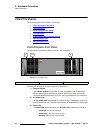
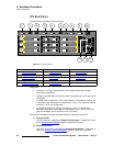
Video Processors
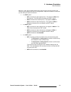
10) Ethernet Port
One RJ-45 connector is provided for 10/100BaseT Ethernet communications.
For multiple connections, use an Ethernet switch on an isolated network.
Six analog and digital connectors are provided for each M/E. Please note:
~ All M/E boards are identical on a VPx. See the “M/E Connectors (VPx)”
section on page 52 for details.
~ Refer to the “A Word About M/E Connector Priority” section on
page 50 for information on M/E connector priority.
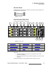
14) Unit ID Selector
One 16-position selector (with physical digits 0 - 15) is provided for setting an
unique
ID on a VPx The selector enables you to assign logical IDs 1 to 16.
By default, a VPx is configured as an
DHCP Client, and it automatically obtains
an IP address when it sees a
DHCP Server. Controller Models SC and LC are
configured (by default) as DHCP Servers.
15) Serial Port
One 9-pin D connector is provided for RS-232 serial communications with the
VPx. In Appendix A, see the “
Serial Connector” section on page 373 for pinouts.
16) AC Connector
One AC Connector is provided to connect the VPx to your AC source.
See the “
Program Output Notes” section on page 57 for more information on VPx outputs.
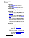
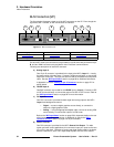
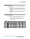
^=tçêÇ=^Äçìí=jLb=`çååÉÅíçê=mêáçêáíó
Depending on your VP or VPx configuration, the M/E connectors on the rear of the chassis
do not necessarily relate 1:1 to the layer buttons in the Controller’s
Layer Control Section.
Please note:
• The Controller’s layer buttons are arranged left-to-right in order of visual priority,
from the lowest (
Mixer 1) to the highest (Mixer 3).
• The M/E boards are arranged in order of electronic priority, from the lowest (M/E
3) to the highest (M/E 1).
• Electronic priority does not equate 1:1 to visual priority, with regard to the silk-
screened labels on the Controller.
11) M/E 1 Connectors 12) M/E 2 Connectors 13) M/E 3 Connectors
Note
Physical digit 0 equates to logical ID 16.
Note
Always ensure that each VPx has a unique ID. During setup,
the
ID is used during various configuration procedures.
Note
Using the Miscellaneous Menu, you can re-define IDs using
numbers
17 - 32. In Chapter 5, refer to the “Miscellaneous
Menu” section on page 196 for details.