


Encore Presentation System • User’s Guide • Rev 04 53
2. Hardware Orientation
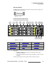
Video Processors
An M/E’s Source Link Output must always be connected to its associated M/E
Source Link Input on the next chassis, and never cross-routed.
S Connect M/E 2’s Source Link Output on Processor 1 to M/E 2’s
Source Link Input on Processor 2.
Please note:
~ In a multi-chassis configuration, the link can extend to all chassis.
~ In all cases, the looped inputs are “pre-scaler.”
In Chapter 3, refer to the “
Program and Source Link Connections” section on
page 98 for details on proper connector usage in wide screen configurations.
In Appendix A, refer to the “
DVI Connector Pinouts” section on page 369 for
pinout details.
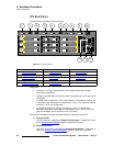
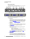
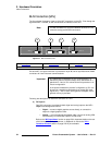
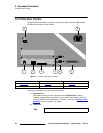
e) Source Link In
One DVI connector is provided for the M/E’s Source Link Input. For wide screen
and multi-screen applications, this connector accepts the looped outputs from the
previous VP or VPx in the chain. An M/E’s
Source Link Input must always be
connected to its associated M/E
Source Link Output on the previous chassis,
and never cross-routed.
In Chapter 3, refer to the “
Program and Source Link Connections” section on
page 98 for details on proper connector usage in wide screen configurations.
In Appendix A, refer to the “
DVI Connector Pinouts” section on page 369 for
pinout details.
f) DVI Input B
One DVI-I connector is provided for both digital and analog inputs to the M/E’s
Layer B and background channel.
~ Digital — connect a digital graphics source directly to this input, or more
typically, connect the output of a digital graphics router.
~ Analog — using the appropriate adapter, connect an analog VGA
source or the output of a VGA router directly to this input.
Refer to the “
M/E Input Notes” section on page 56 for details on the use of this
connector’s analog component. In Appendix A, refer to the “
DVI-I Connector
Pinouts” section on page 370 for pinout details.
g) HD/SDI Input B
One BNC connector is provided for the HD/SDI input to Layer B. Connect an SDI
or HDTV source directly, or connect the output of an SDI or HDTV router. Refer to
the “
M/E Input Notes” section on page 56 for additional information.
h) Analog Input B
One 15-pin D connector is provided for the input to the M/E’s Layer B — visually,
the higher priority of the two by default. Connect a VGA source or the output of a
VGA router. This input can also be used for composite and component video.
See the “
M/E Input Notes” section on page 56 for information about video inputs.
In Appendix A, see the “
Analog 15-pin D Connector” section on page 371 for
pinout details.