46 Encore Presentation System • User’s Guide • Rev 04
2. Hardware Orientation
Video Processors
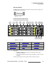
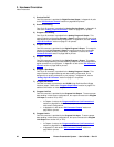
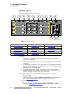
1) Preview Out DVI
One DVI connector is provided for Digital Preview Output. In Appendix A, refer
to the “
DVI Connector Pinouts” section on page 369 for pinouts.
2) Preview Out Analog
One 15-pin D connector is provided for Analog Preview Output. In Appendix A,
refer to the “
Analog 15-pin D Connector” section on page 371 for pinouts.
3) Program 2 Out Analog
One 15-pin D connector is provided for the Analog Program 2 Output. This
output is identical to the analog
Program 1 Output, except that it does not include
edge feathering and data doubling components. In Appendix A, see the “
Analog
15-pin D Connector” section on page 371 for pinouts.
4) Program 2 Out DVI
One DVI connector is provided for the Digital Program 2 Output. This output is
identical to the digital
Program 1 Output, except that it does not include edge
feathering and data doubling components. In Appendix A, refer to the “
DVI
Connector Pinouts” section on page 369 for pinouts.
5) Program 1 Out DVI
One DVI connector is provided for the Digital Program 1 Output. This output
includes all edge feathering and data doubling components, and is designed for a
digital connection to your projector. In Appendix A, refer to the “
DVI Connector
Pinouts” section on page 369 for pinouts.
6) Program 1 Out Analog
One 15-pin D connector is provided for the Analog Program 1 Output. This
output includes all edge feathering and data doubling components, and is
designed for an analog connection to your projector. In Appendix A, see the
“
Analog 15-pin D Connector” section on page 371 for pinouts.
7) Program Out HD/SDI
One BNC connector is provided for the HD/SDI (High Definition/Serial Digital
Interface) output. Refer to the “
Program Output Notes” section on page 57 for
additional information on video outputs.
8) Program Link Out
One DVI connector is provided for the Program Link Output. To ensure proper
data doubling in wide screen configurations, this output connects to the
Program
Link Input
on another VP (or VPx).
~ In Chapter 3, refer to the “Program and Source Link Connections”
section on page 98 for details on the proper use of the connectors in
wide screen configurations.
~ In Appendix A, refer to the “DVI Connector Pinouts” section on
page 369 for pinouts.
9) Program Link In
One DVI connector is provided for the Program Link Input. To ensure proper
data doubling in wide screen configurations, this input connects to the
Program
Link Output
from another VP (or VPx).
~ In Chapter 3, refer to the “Program and Source Link Connections”
section on page 98 for details on wide screen configurations.
~ In Appendix A, refer to the “DVI Connector Pinouts” section on
page 369 for pinouts.


