Checking Signal Status
CTS 710 SONET Test Set User Manual
3–57
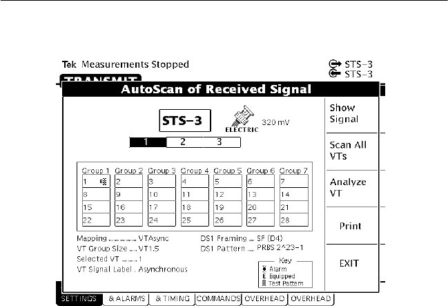
Figure 3–19: Viewing Tributary Signal Structure
Determining the Payload Pattern and Framing (Add/Drop/Test Option
Only)
To search for a pattern in the data of the received signal or determine
the framing, select Analyze VT. After you select Analyze VT, the
CTS 710 scans the selected VT in the received signal to see if it
there is a pattern within the data and if the signal is framed. If a
pattern is found, it is displayed below the payload map on the Pattern
line (for example, PRBS 2^23–1). If the CTS 710 is unable to find a
pattern within the signal, it displays Unknown on the Pattern line.
The CTS 710 will display Unframed or Framed on the Framing line.
To scan every VT in the received signal, select Scan All VTs. As the
CTS 710 scans the signal, it will indicate for each VT whether it has
detected an alarm, whther the VT is equipped, and whether a test
pattern was found in the VT. The key which describes each of the
indicators is located in the lower, right corner of the AutoScan dialog
box (see Figures 3–19 and 3–20).
