


Functional Overview
2–2
CTS 710 SONET Test Set User Manual
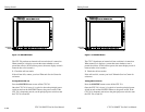
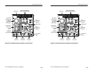
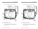
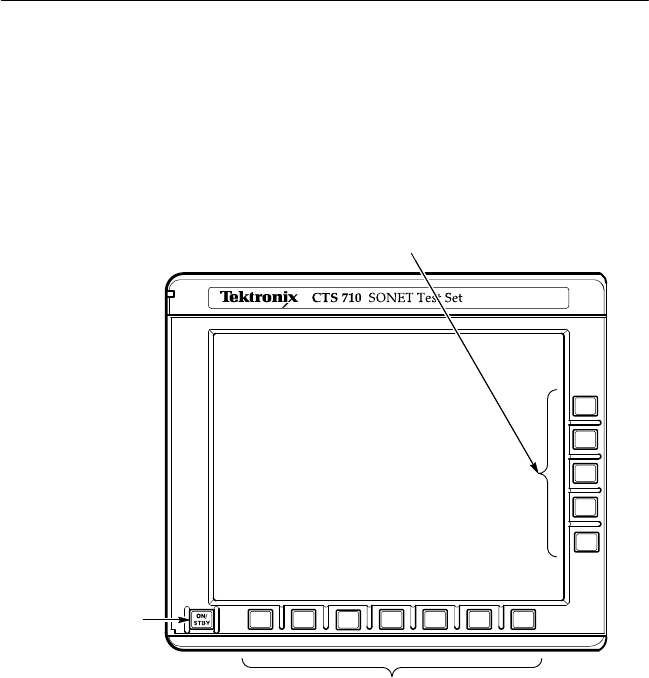
Front-Panel Controls, Indicators, and Connectors
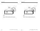
Figures 2–1 and 2–2 identify the controls, indicators, and connectors
located on the front panel of the CTS 710 SONET Test Set.
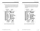
ON/STBY Switch
(the principal
power switch is on
the rear panel)
These buttons select the
pages of the current menu.
These buttons assign the displayed choice to the
selected parameter or execute the selected action.
Figure 2–1: Controls Located Around the Display
Functional Overview
2–2
CTS 710 SONET Test Set User Manual
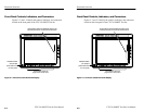
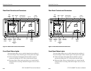
Front-Panel Controls, Indicators, and Connectors
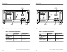
Figures 2–1 and 2–2 identify the controls, indicators, and connectors
located on the front panel of the CTS 710 SONET Test Set.
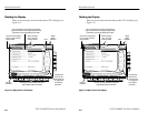
ON/STBY Switch
(the principal
power switch is on
the rear panel)
These buttons select the
pages of the current menu.
These buttons assign the displayed choice to the
selected parameter or execute the selected action.
Figure 2–1: Controls Located Around the Display