


Appendix G: Rear-Panel Connectors
G–6
CTS 710 SONET Test Set User Manual
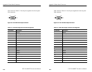
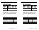
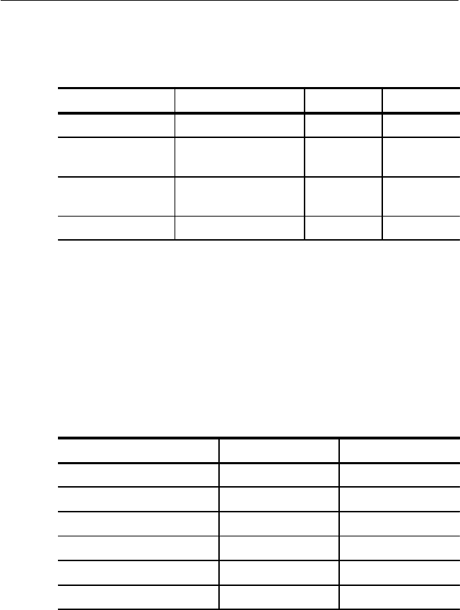
Table G–4: Overhead Channels Dropped
Dropped Channel
Bytes Dropped Data Rate Clock Rate
Section DCC D1, D2, D3 192 kbps 216 kHz
Line DCC D4, D5, D6, D7, D8,
D9, D10, D11, D12
576 kbps 2.16 MHz
Section User
Channel
F1 64 kbps 72 kHz
Path User Channel F2 64 kbps 72 kHz
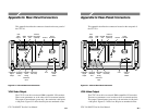
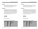
Table G–5 summarizes the data signal pin assignments on the
Overhead Add/Drop port. Table G–6 summarizes the additional pin
assignments on the Overhead Add/Drop port. The signal lines listed
in Table G–5 can drive 100 W, differential TTL lines. The signal
lines are terminated with a 100 W impedance and can drive 100 W
lines.
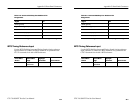
Table G–5: Overhead Add/Drop Port Data Signal Pin
Assignments
Signal +Pin –Pin
Added Tx Data (input) 4 22
Added Tx Clock (output) 5 23
Tx Common (ground) 37 –
Dropped Rx Data (output) 6 24
Dropped Rx Clock (output) 8 26
Rx Common (ground) 20 –
Appendix G: Rear-Panel Connectors
G–6
CTS 710 SONET Test Set User Manual
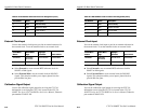
Table G–4: Overhead Channels Dropped
Dropped Channel
Bytes Dropped Data Rate Clock Rate
Section DCC D1, D2, D3 192 kbps 216 kHz
Line DCC D4, D5, D6, D7, D8,
D9, D10, D11, D12
576 kbps 2.16 MHz
Section User
Channel
F1 64 kbps 72 kHz
Path User Channel F2 64 kbps 72 kHz
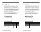
Table G–5 summarizes the data signal pin assignments on the
Overhead Add/Drop port. Table G–6 summarizes the additional pin
assignments on the Overhead Add/Drop port. The signal lines listed
in Table G–5 can drive 100 W, differential TTL lines. The signal
lines are terminated with a 100 W impedance and can drive 100 W
lines.
Table G–5: Overhead Add/Drop Port Data Signal Pin
Assignments
Signal +Pin –Pin
Added Tx Data (input) 4 22
Added Tx Clock (output) 5 23
Tx Common (ground) 37 –
Dropped Rx Data (output) 6 24
Dropped Rx Clock (output) 8 26
Rx Common (ground) 20 –